Geek Articles
How Your Camera’s Focus Bracketing System Works
For many years, photographers have had focus-stacking programs like Helicon Focus and Zerene Stacker. You can now get the capability in some general-purpose image editors like Lightroom and Capture One Pro. Focus stacking software takes as input a series of images of the same subject with the focal plane in a different place in each image. The software goes through the images and assembles an image containing the sharpest portions of each of the input images. You can use focus stacking to achieve a depth of field impossible in a single shot. Also, you can use your lenses at their optimum aperture, instead of, in search for more depth of field, stopping down so far that diffraction adversely impacts detail.
It’s a great addition to your photographic toolkit. But there’s been a problem.
Especially for macro photography at moderate to high magnifications, the capture of images to feed to the stacking programs hasn’t been easy. As the magnification goes up, you need a lot more images – sometimes hundreds of them – and the precision of the steps gets harder to control. You could try to move the focus plane manually, but that has been hit-and-miss and there was always the risk of jostling the camera in the middle of a stack. You could buy a focusing rail driven by a stepper motor from a company like Cognisys. You could buy an app to control the focusing of some lenses on some cameras. But to use those apps and devices, you’d need to have a reasonably comprehensive knowledge of geometric optics. Geometric optics isn’t rocket science. Anyone who remembers their high school algebra and is diligent enough to bone up on it can master it. If you’d like to give it a shot, read Chapter 3 of this paper. From what I’ve seen interacting with other photographers on the ‘net, mastery of geometric optics is uncommon.
Things are different now.
Many contemporary cameras have a feature that can sidestep most of the theory and avoid the need for rails and apps. Nikon calls it Focus Shift Shooting. Fujifilm, Olympus, Hasselblad, Sony, and Canon call it Focus Bracketing. Phase One calls it the Focus Stack Tool. I have tested both the Fuji and Nikon implementations on half a dozen cameras, and it works on all of them — although I far prefer the Fuji implementations to the Nikon ones. These features only work with autofocus lenses, since they depend on the camera’s ability to change how the lens is focused.
The focus bracketing systems on the cameras I’ve tested do pretty much what they’re supposed to do, and the manufacturer’s documentation explains, sometimes cryptically, how to operate them. But it doesn’t explain the theory behind their operation, or how to pick the settings. From what I’ve seen on the ‘net, there is a great deal of confusion about those things. This piece is intended to supply the missing information.
Whatever you call them, the availability of camera-integrated automated focus shift has democratized automatic focus stacking, giving many folks with weak knowledge of geometrical optics the opportunity to try things that were previously only the province of experts. Those people don’t have a quantitative understanding of the depth of field/depth of focus/circles of confusion and aren’t capable of moving back and forth between image and object space, both previously skills necessary for well-controlled automatic focus stacking.
If that last sentence confuses you, don’t worry for two reasons: I’m going to explain everything you need to know, and automated focus bracketing systems do a lot of the math for you, so there’s stuff you’d have to learn if you were doing this manually that you don’t have to pay attention to now.
I will attempt to explain how these focus bracketing systems work, assuming nothing about your knowledge of the geometrical optics behind depth of field calculations, though I’ll assume that you’re familiar with the concept of depth of field. I will do a lot of simplification and I’ll avoid math wherever I can.
Here goes.
The Nikon and Fuji systems all work in about the same way, though the details vary. I suspect — but do not know for sure – that the focus-shifting systems on other cameras are much the same. There is a logic to how these systems operate that is compelling, and I’d be surprised if a camera manufacturer came up with a completely different approach.
Depth of Field
First, let’s look at the problem these systems are intended to solve.
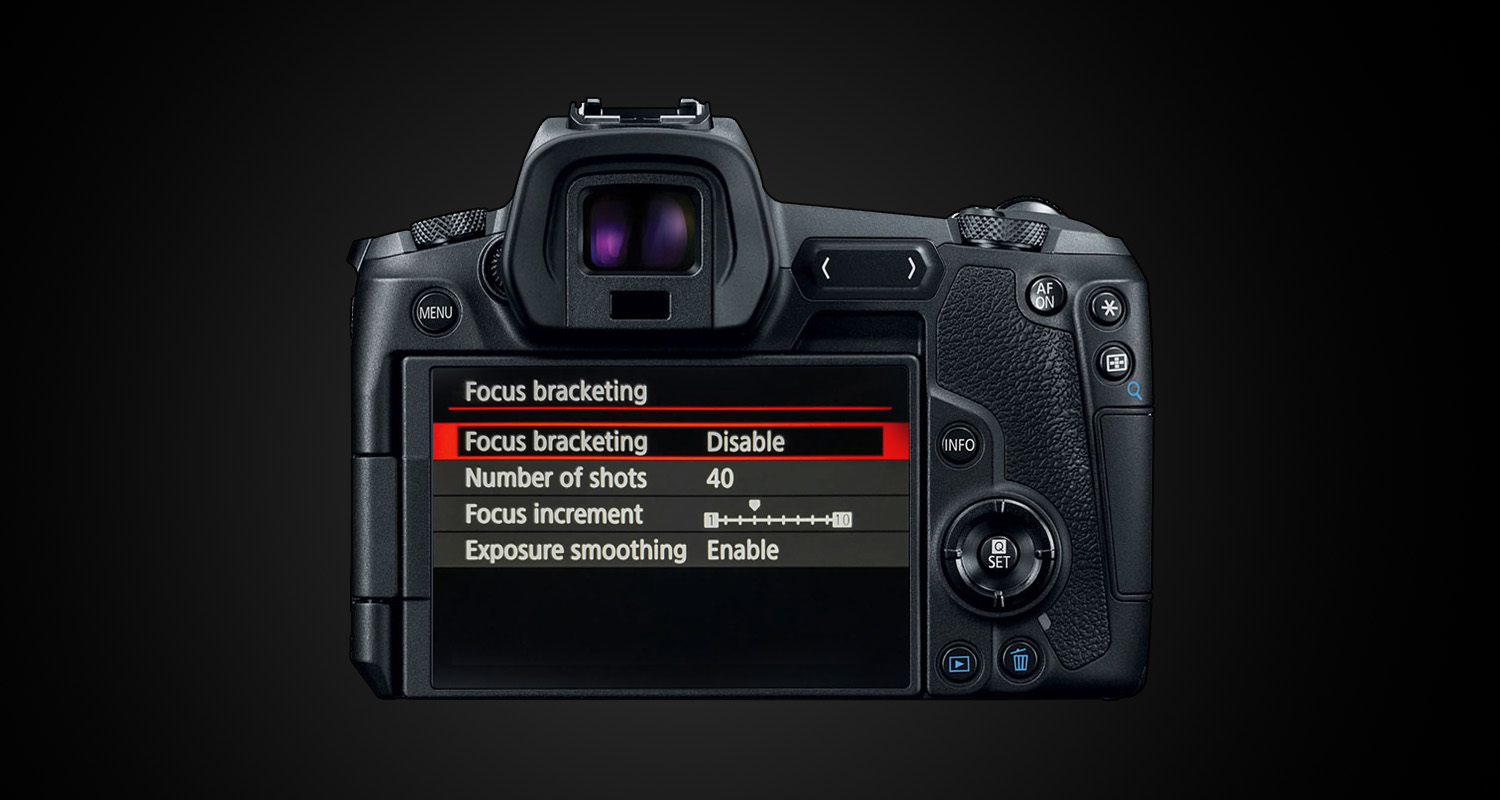
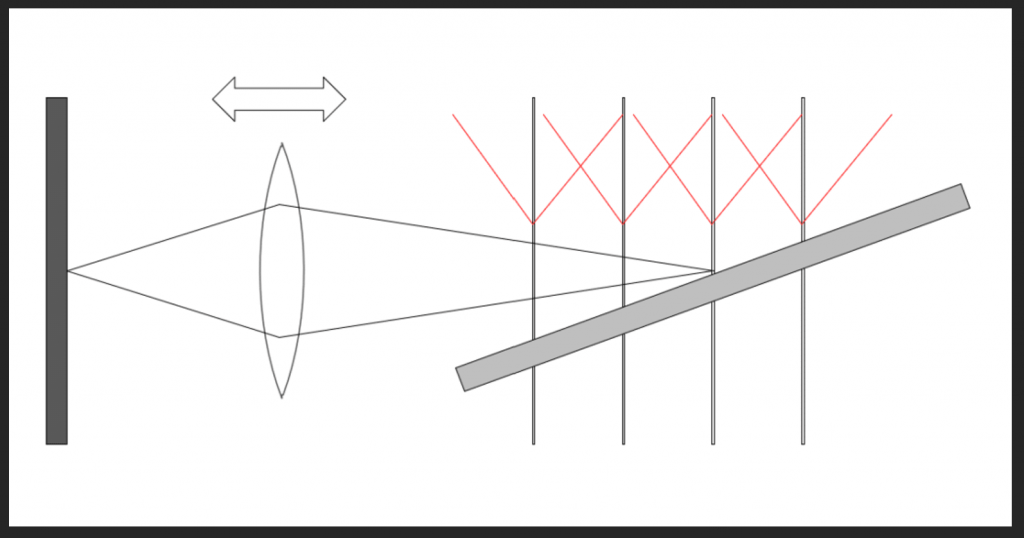
On the left, we have the camera, represented schematically by the sensor (the gray part on the far left) and the lens. The subject on the right side of the sketch is a ramp rising as it becomes more distant. Focus bracketing or focus shifting (I’ll use the terms interchangeably) makes successive exposures, moving the plane of focus in each one. Nikon and Fuji both move the plane of sharp focus progressively further from the camera; others offer more possibilities. I’ve marked possible focal planes at four places with vertical lines, and I’ve sketched in how the sharpness might vary with distance at each location. Don’t put much stock in the precise shapes of those “haystacks”, but do understand that, for every focus metric (there are dozens) that I’ve looked at, as you move further away from the focal plane, sharpness at first falls off gradually, then rapidly, then gradually again. That generality is correctly represented in the haystacks.
The width of the haystacks is determined by the f-stop of the lens, and some other things that you won’t have to worry about (I’ll explain that later).
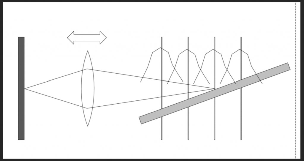
As the step sizes get bigger, the planes of focus become more separated, but the haystacks remain the same, with the result that there is progressively less overlap:
Note the places where the haystacks cross. The amount of sharpness at those points is the worst sharpness available in the completed set of captures. We want to control that worst-case sharpness by selecting the proper step size.
Here’s the first rule of focus bracketing.
All calculations of the desired step sizes should stem from choosing the minimum acceptable sharpness, and picking step sizes that are small enough to give you the sharpness you desire, and not so small that you waste a lot of exposures getting the job done.
Depth of Focus
Now let’s leave the lens focusing alone, move the target, and consider what happens when the image on the sensor is out of focus:
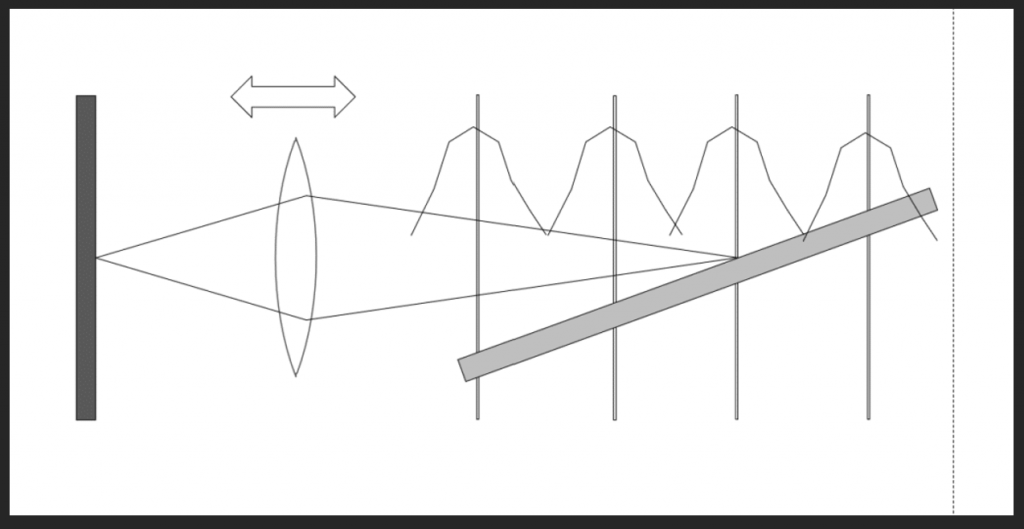
In the top part of the drawing, the iris diaphragm is represented schematically by the two dark rectangles blocking off part of the lens. The focal plane can fall ahead of, or behind, the sensor. When that occurs, we say that the lens is misfocused, or defocused (with respect to the subject).
- When the focal point is ahead of the sensor (the red lines), we say the subject is back-focused.
- When the focal point is behind the sensor (the blue lines), we say the subject is front-focused.
- When the image side focal plane falls directly on the sensor (the black lines), we say the subject is in focus.
Image Space and Object Space
There are two ways of looking at focus depth and defocus blur, as illustrated by the above. If we consider the effect on the subject side of the lens (as opposed to the sensor side), we talk about object space and depth of field. Occasionally, people talk about subject space. Confusing the grammarians, it subject space is the same as object space. If we concern ourselves with what happens on the sensor, or image side of the lens, we talk about image space and depth of focus.
Here is the second rule of focus bracketing systems like Nikon’s and Fuji’s.
They work entirely in image space.
They don’t pay any attention to the focal length of the lens or the subject distance, although they do pay attention to the f-stop. And the surprising and wonderful thing is that, from the point of view of print sharpness, that’s all they need to do*. Well away from the point of focus and near the lens axis, the blur circle of a normal (not apodized, not Petzval) photographic lens can be reasonably well modeled by an image of the diaphragm opening, which approximates a circle**. For most of today’s lenses, that means we’re talking about filled-in blur circles called circles of confusion (CoC). The thing that determines how much blur we’ll see in the image is the diameter of that circle. The size of the CoCs, which are illustrated in the lower part of the above figure. Note that no matter whether the image on the sensor is front-focused or back-focused, the size of the CoC is determined by the amount of misfocusing on the sensor side of the lens (in image space). If you will forgive a bit of math, the diameter of the CoC is the amount of image space misfocus over the f-stop, but you don’t even need to know that; the camera will figure that out for you.
Picking an Acceptable CoC
In the film era, the CoC diameter was usually measured in millimeters. For 35 mm work, the diameter for the CoC that was used to construct depth of field tables was on the order of 0.03 mm. For critical work with today’s high-resolution digital cameras, that’s way too big. One way to get a handle on the effect on the image of a 0.03 mm diameter CoC is to figure out how many such circles it would take to fill the height of a 35 mm landscape orientation frame. That’s 720 circles. The vertical resolution of a high-res full-frame camera is about 6000 pixels. You can see that you’re giving up a lot of sharpness if you use a 0.03 mm CoC to compute depth of field.
These days CoC diameter is usually measured in micrometers, or um. There are 1000 um to a mm. So, the traditional CoC diameter is 30 um. Sensor pitches for high-res cameras run around 4 um. For roughly equal contribution of sensor pixel aperture blur and defocus blur, you’d set the CoC for depth of field computations to about 4 um. That produces depths of fields that are much smaller (not paper-thin for normal circumstances but going in that direction) than we’re used to seeing in DOF tables.
With a modern high-resolution camera, 30 um CoCs produce images that look pretty blurry. Depending on your subject matter, the size of your intended prints, and the esthetics of the scene, I recommend using 15 um as a default, and 7.5 um for the parts of the image that you want to look reasonably sharp.
If you want the most out of your camera, the right worst-case CoC for stacking and focus bracketing is on the order of the pixel pitch of the camera, or about 4 um for high-res cameras. If you want the ultimate precision, you could go as low as half that with modest improvement. For non-critical work, twice that will be just fine.
CoCs for focus bracketed images
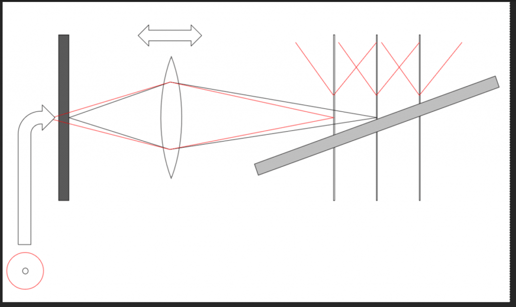
How do the CoCs affect the sharpness of our ramp? Let’s take a look:
I’ve drawn in red the way the CoCs for each of the four focused positions vary as you move away from those positions. Perhaps confusingly, I’ve drawn them on the object side of the lens, even though they exist on the image side. In my defense, when I tried it the other way around, it was even more confusing. If you prefer, you can think of the red plots in the above image as the projection of the CoCs back into the object space, where they are called disks of confusion. In the each of the focused planes, the CoCs are zero (there will still be other sources of blur, such as diffraction and lens aberrations). As you move away from those planes, the CoC diameters increase approximately linearly (they do increase precisely linearly in image space, but when we project them into object space the straight lines become curves).
The thick sawtooth red line in the diagram below shows the biggest CoCs that stacking software will see as it looks down the ramp:
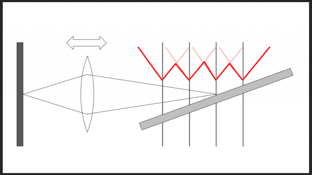
Imagine you are the stacking software deciding which input image to use to create the output image. Starting from nearer to the camera than the nearest focal plane, the CoC decreases as you move towards that plane, then widens again. When you get halfway to the second focal plane, it becomes sharper, and you can switch over to that image, and use it until you are halfway between the second and third planes, whereupon you can switch over to the image from the third plane, and so on until you reach the end of the captured images.
Similarly, if you as a human are going to select the image in which some object along the ramp is the sharpest, the biggest CoC you’ll see is half of the CoC seen in one plane when focused on the adjacent plane.
So, now you know how to pick a worst-case CoC for bracketing and stacking, and you know how the CoCs in your captures will affect the CoCs in your stacked image or in the image(s) that you manually select from your captures. But there’s one more thing you need to know.
How the Step Size Affects the CoC
The final piece of the puzzle is: when using focus bracketing, how do the shot-to-shot CoCs change with camera settings?
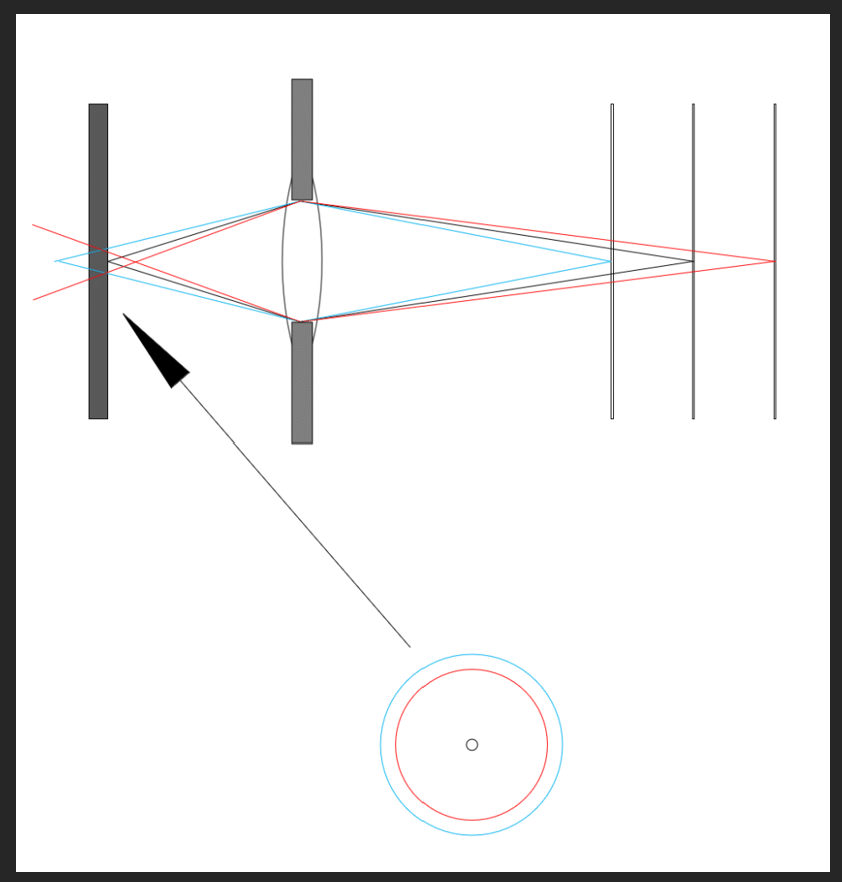
To deal with that question simply, we’re going to have to leave object space, and think like the camera does, in image space. The next diagram shows what happens when you focus on the middle plane but examine the blur in the nearer plane.
The red circle indicates the blur circle in the sensor plane for an object in the near plane when the camera is focused on the middle plane. Let’s call that the single-step-CoC. When you use focus bracketing, what controls its diameter?
The surprising answer is just the step size. That’s right. Not the focal length of the lens. Not the distance from the camera to the subject. Not even the f-stop. The camera takes care of all that. And, because we’re working in image space, the step size in micrometers can – and will – remain constant throughout the series.
You don’t need to understand how the camera manages that feat to successfully use focus bracketing, but for those who are interested, I’ll explain now. The diameter of the blur circle is the distance between the image space focal plane and the sensor, divided by the f-stop. The subject distance doesn’t enter into the calculations, since we’re working in image space. The focal length of the lens doesn’t matter, either, since it is handled by considering the f-stop. So all the camera has to do is look at the f-stop and the step size, and move the image side-focal plane so that the blur circle doesn’t change when you change the f-stop.
The beauty of this is that you can think of the step size strictly in terms of the blur circle that you are willing to have.
With the Fujifilm GFX 50, GFX 50R, GFX 50S II, GFX 100, and GFX 100S, it’s really simple: the single-step CoC in um is twice the step size, which means that the size of the largest blur circle you’re going to see in a stack from a set of captures (the worst-case CoC) is the step size in um. Step size = 1 means you’ll not need to use an image with CoC of over 1 um, which is ridiculously small for a 3.72 um camera. Step size of 4 means that the largest blur
circle you’ll have to take is 4 um, which is about the pixel pitch, and not a bad place to start. With a step size of 10, you’ll have to use blur circles as large as two and a half times the pixel pitch, which is starting to get a bit sloppy. If you want to see the experimental results for the GFX 100, look here.
The Nikon Z7 step sizes are coarser. With the Z7, the minimum single-step CoC is about 22 um (so the worst-case CoC is half that), and step size 9 gets you about 200 um (100um worst case for a stack). There are some glitches that mean that sometimes, especially at the lower step sizes, you won’t get the even step sizes that you should. Some experimentation will be required, but step size 1 will mean that the largest blur circle you’ll have to deal with is 11 um. Things get pretty coarse at the upper end: step size = 9 means you’ll have to be ready for blur circles as large as 100 um, which is pretty sloppy.
Those of you with other cameras, don’t worry. I’ve got some things you can do further on in this post.
Putting Focus Shifting to Work for Stacking
With both the Nikon and the Fuji systems, the first step is to pick the step size based on your tolerance for blur in the stacked result. Then pick the near focal distance. If you want to avoid mathematics not explained in this post, experiment to see how many shots will be necessary to get to the desired far focal distance, varying the f-stop if you wish (a narrower f-stop will require fewer steps; f/11 will require half as many steps as f/5.6.).*** Once you’ve done this a few times, you’ll have a pretty good idea of how many steps it will take. If the lens is longer or the subject is closer, it will take more steps. When you get really close, it will take a lot of steps, and you may wish to allow more blur by making the step size larger. At 1:1, image space is a mirror of object space, and the step size in the image field will be the step size in the object field; that means steps in the object field of a few micrometers.
An Example
Let’s walk through how you’d plan for a shoot, assuming you have a GFX 100S. Let’s say you are stacking images, using a program like Helicon Focus (my current favorite). Let’s further say that it’s a macro subject. Your first decision is the largest blur circle you’ll want Helicon Focus to have to deal with. You decide that you’ll be fine if it’s 6 um (which is a nice place to start if you have no idea), so you set the step size to 6. You focus a bit nearer than the closest thing that you want to be sharp, set the number of steps to a couple of hundred, and tell the camera to start making exposures while you watch the focal plane move in the LCD finder on the back of the camera (don’t use the EVF or you might jostle the camera). When the focal plane gets far enough away, note the number of exposures and stop the camera. Did it make more exposures than you want to deal with? Stop the lens down a bit and try again. When you are getting about the right number of exposures, delete all your test images and start making real ones.
Fuji GFX cameras have a mode where the camera determines the number of images. They use a step size of 5 for that determination, which also seems like a reasonable compromise. They don’t document that choice, and I had to find it out by reverse engineering the algorithm.
What if you’re using some other camera besides Nikon or Fuji?
I’ve conducted experiments to measure the step sizes of several Nikon and Fuji cameras. Those tests are somewhat laborious, and I don’t recommend that you try to replicate them if all you want is to determine what step size to use if I’ve not measured your chosen camera. What you need to do is find the largest step size you can get away with your camera, your lenses, and your subject matter. To do that you’ll need to conduct an experiment, but the results of that experiment will probably be broadly applicable to all of your photography that uses that gear and subject matter.
You’ll be shooting the same subject matter with different step sizes. Before you begin, you’ll need to find out what your camera calls step size.
- Olympus calls step size focus differential; the choices are 1 through 10.
- Canon calls step size focus increment; the choices are 1 through 10.
- Hasselblad, not reinventing the wheel here, calls step size step size; the choices are Extra Small, Small, Medium, Large, and Extra Large.
Set up your chosen camera and lens on a tripod, aimed at a subject like what you intend to use for focus stacking. Set the step size to a middle value. Note the direction in that the focus plane will change. Some cameras let you choose that. Some don’t. I’ll assume it goes from near to far.
- Focus on the nearest part of your subject.
- Set the number of shots to a fairly high number, like 20.
- Make a series of images.
- Bring them into your favorite raw developer.
- Develop them all the way you usually do.
- Pick one spot in the image and find the shot in the series where that spot is the sharpest.
- Look at that spot in the shots immediately before and after that shot.
- Can you see any difference in sharpness in the spot you picked?
- If no, the step size could be bigger.
- If yes, is that amount of blur acceptable to you?
- If yes, then you’re done; use the step size you used for the test for your actual photography.
- If no, try again with a smaller step size.
There’s a conservative bias built into this test. The actual worst-case blur that your stacking software will see will be half of what you saw in your test. The cost of that conservatism is a few more shots than necessary. If that’s a big deal for you, you could go to a coarser step size. In the GFX cameras, you could double the step size, but there’s no guarantee that your camera’s step sizes are linear like the GFX.
You can change focal lengths, and, if your new lens is about as sharp as the one you used for the test, the results will still apply. You can change the subject distance and the results will also apply. To some extent, you can change the subject or lighting and use the same step size.
To review:
- You need to decide on the step size (and therefore the worst-case CoC) for your intended subject material and your usage of the images. If you have a Nikon or Fuji camera, use the numbers I recommended. If you have another camera, do the test above.
- In some cases, the camera can make some assumptions and pick the number of images required for the stack. If not, or if you’re not using that mode, make a test run to determine that. There is little penalty for too many images other than your time and space on the flash card.
- The camera will make corrections for changed subject distance, lens focal length, and the aperture you choose.
Enjoy!
*One detail that is not reflected in the top drawing is that, in object space, the haystacks get broader as you get further from the camera, but the camera compensates for that by making the steps equal in image space, which means they get further apart as you get further away from the camera in object space.
**When the lens is only slightly misfocused, the blur on the sensor is caused by a combination of defocusing, lens aberrations, diffraction, and the pixel aperture of the sensor. You can get a rough idea of the diameter of the combined blur circle by computing the square root of the sum of the squares of the diameter of each of those four blur circles.
***There are ways to calculate the number of steps required, but that requires a knowledge of geometric optics.
Related Reading
- Why Manufacturers Make a Specific Camera Lens
- The Great Flange-to-Sensor Distance Article: Part 1 — Cine Cameras
- Practical Use of Field Curvature: Wide and Telephoto Primes
- Things You Don’t Know About Stopping Down Your Lens
Author: Jim Kasson
I’ve been a photographer since high school, and an electrical engineer all of my professional life. The two things came together for a while. From 1989 until the middle of 1995, I worked as an IBM Fellow at the Almaden Research laboratory south of San Jose, CA. For those six years, my principal area of research was color management, color processing for digital photography, and color transformations such as gamut mapping. At other times in my career, I researched speech recognition and speech bandwidth compression and developed data acquisition and process control computer systems, telephone switching systems, and data communication systems. I retired in 2000, and for the last 22 years when I’m not serving on NFP boards unrelated to photography, I’ve been spending most of my free time making photographs.-
t_linn
-
Jim Kasson
-
Jim Kasson
-
Chris Newman
-
Nem Tom
-
waterengineer
-
Chris Jankowski
-
Corey
-
Chris Jankowski
-
Athanasius Kirchner
