Teardowns and Disassembly
A Peek Inside the Canon 24-70 f/4 IS
If we knew what we were doing it wouldn’t be called research, would it? Albert Einstein
Of course we had to do it. One of them was soft, you see, and we were really curious about how that Macro mode switch worked and . . . . OK, we just wanted to. Actually, we’ve found the new 24-70 f/4 IS is a most interesting lens inside.
So as usual, Aaron is doing the disassembly while I’m doing the photography and writing.
Up Front First
There’s a plastic cosmetic ring that pops out.
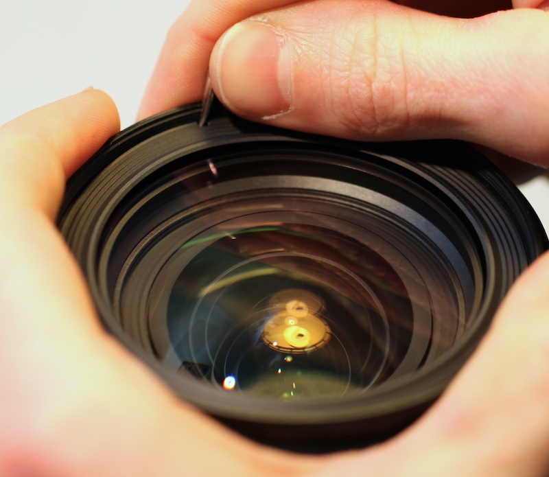
Which uncovers the 6 screws holding the front group in place. Like the 24-70 f/2.8 Mk II (and unlike the Mk I) there are no adjusting tilt or centering screws on the front element.
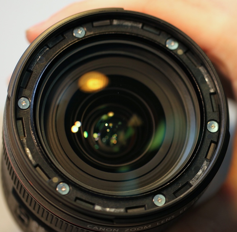
With those out the front group is comes right out. Hopefully this will keep replacement costs for a scratched front element low.
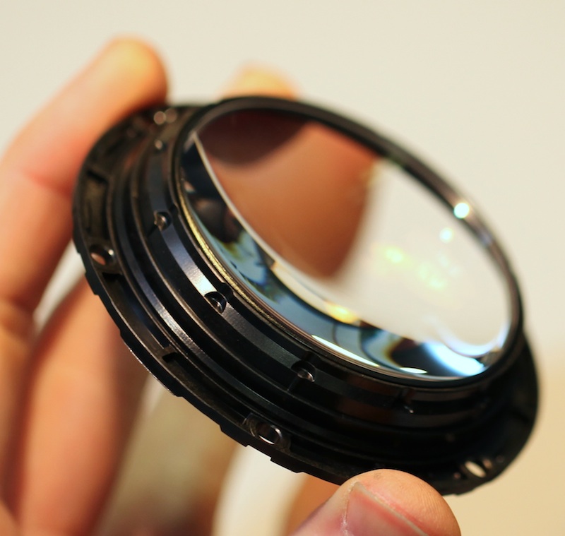
Underneath the front element, the distal barrel / filter ring is held on by an arrangement we’ve never encountered before. Each of the 6 screws mounts through a metal sleeve, compressing a spring as it tightens the front barrel in place.
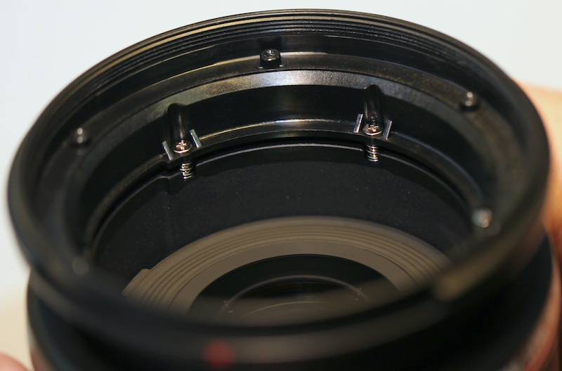
As is often the case when we see something new, we aren’t certain what the purpose is. Our first thought was shock absorbing, but the screws are tightened down pretty well so there’s no spring action. Our second thought was front element tilt (by tilting the whole barrel) but we see no shims or washers that would (we think) be used if that were the purpose. On the other hand, one of the lenses we received that was soft at 70mm had a couple of these screws a half turn loose and was much better after they were tightened.
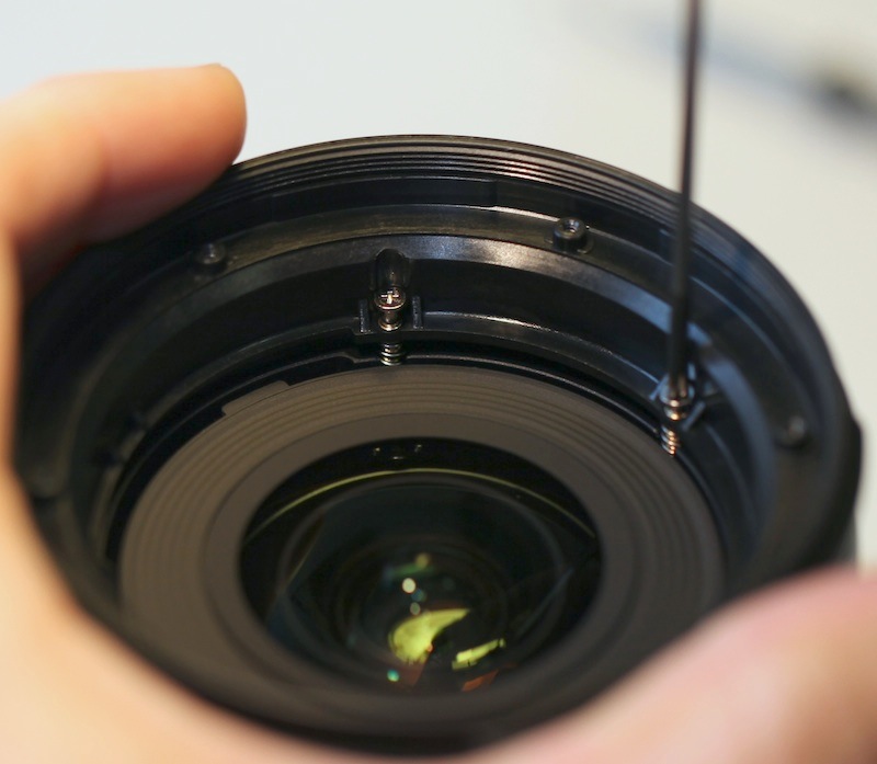
Anyway, if you take these screws out, the distal barrel / filter ring comes right off. (Since we did not know their purpose, we considered not messing with them. For about 2 seconds.)
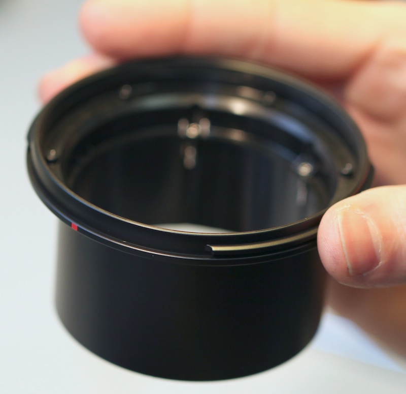
Again, this should make a simple repair when a filter ring breaks. Just for demonstration purposes, a couple of shots with the internal barrel zoomed out to 70mm and back to 24mm (retracted).
We left the tube/spring assemblies in place with the screws removed to show them again. Maybe one of you can explain what they are. (That’s a subtle hint to any Canon techs who are visiting. We haven’t outed anyone else who told us stuff we aren’t supposed to know. We won’t out you either — we’ll just say we figured it out ourselves, OK?)
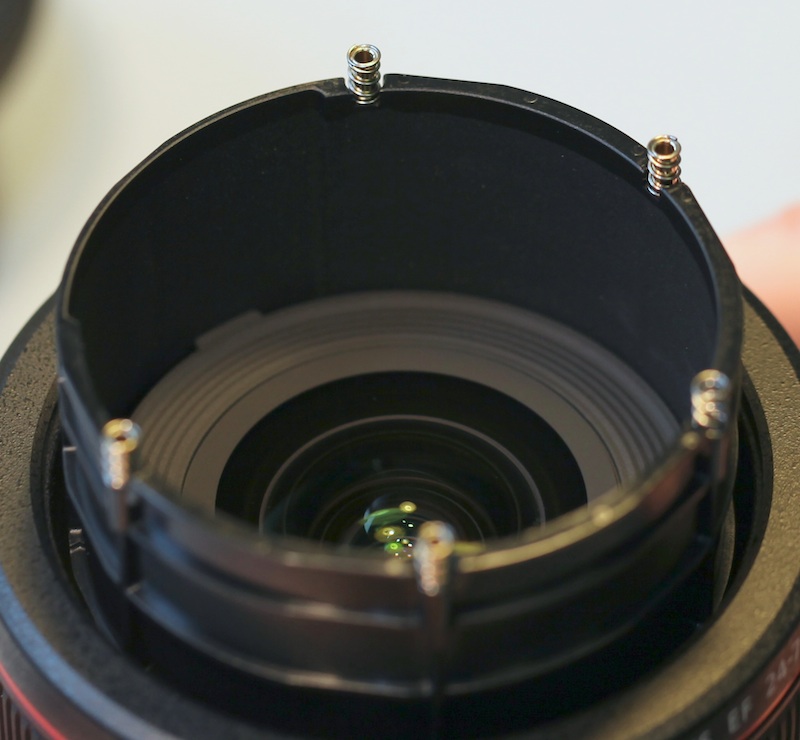
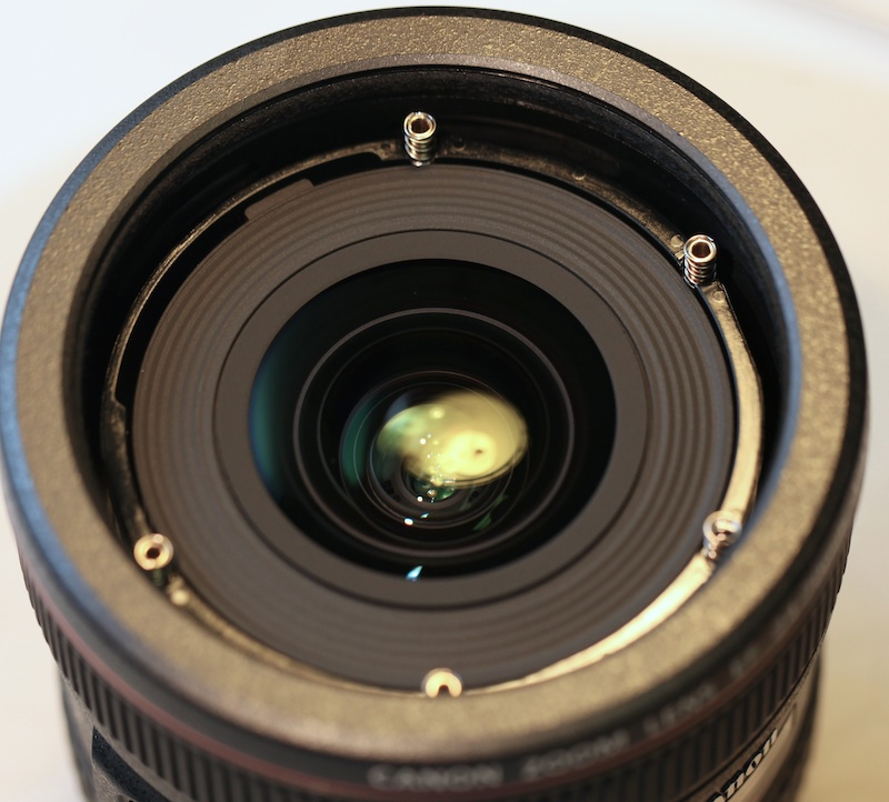
BTW – this second element is one of the focusing elements. Notice the focus key at 11 o’clock in the picture above. OK, that’s all there is to see from the front of the lens, so have a cup of coffee while we put this part back together and move to the back side.
The Back Side is More Interesting
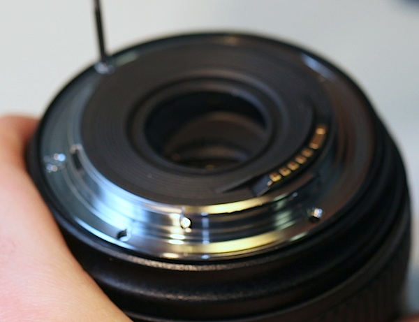
The back comes off in the usual way, showing us the main PCB. Other than a rather amazing 8 flexes that have to be unplugged it’s pretty routine.
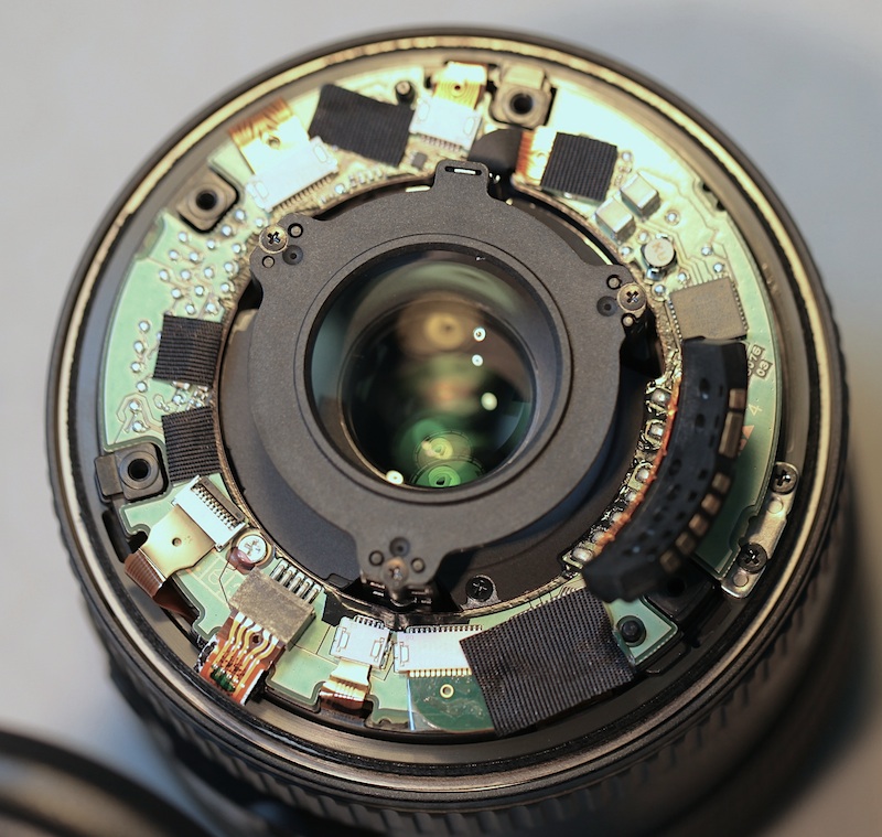
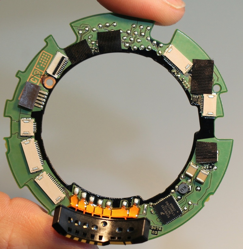
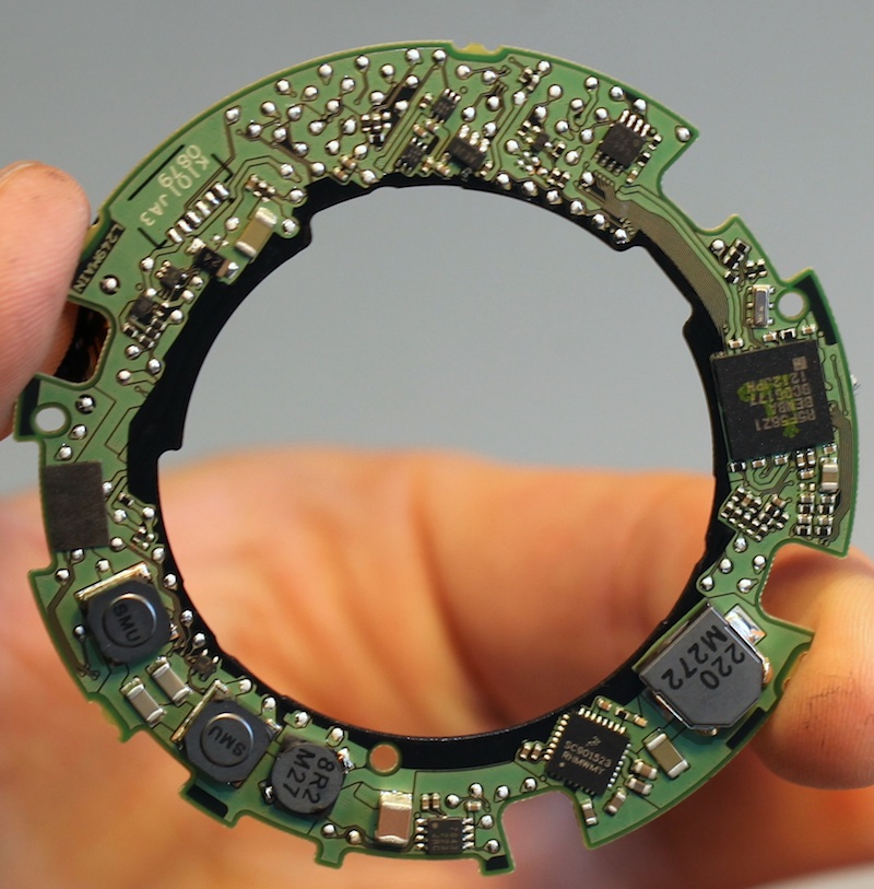
The PCB has a bit more circuitry than older lenses, laid out in Canon’s usual efficient and orderly fashion. There are a number of flush-mounted components, many covered by heavy electrical shielding tape.
At this point we come to another thing we’ve never really seen before, at least not to this degree. The single rear element is sort of on stilts, projecting out to the back of the lens all by it’s lonesome – at least with the lens racked out to 24mm (more on that later). That’s a big gap between the rear element and the next element forward.
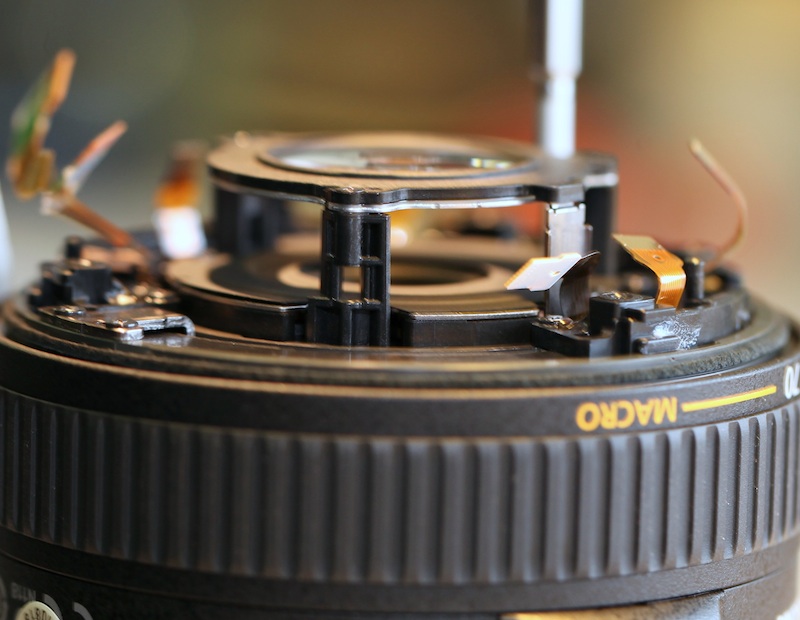
There are a healthy number of screws (8 if I recall correctly) holding the rear barrel in place. Once it’s removed we again see Canon’s usual tightly organized flex runs to the switches in the barrel. I know it doesn’t make a bit of difference in what kind of pictures it takes, but it makes me feel comfortable knowing some engineer has taken the time to map out each flex run, etc. Wish some other manufacturers did.
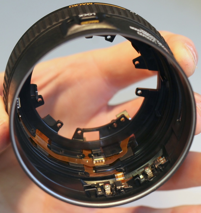
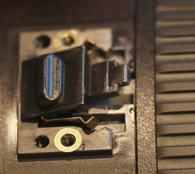
One thing I was very interested to see was the zoom lock-macro switch and how it worked since this is a first. The good news is the switch is easily removed or changed from outside with no lens disassembly — it’s a simple mechanical switch with a plastic tab that slips under the zoom ring fully to lock, and must be pulled back against a spring to allow Macro work.
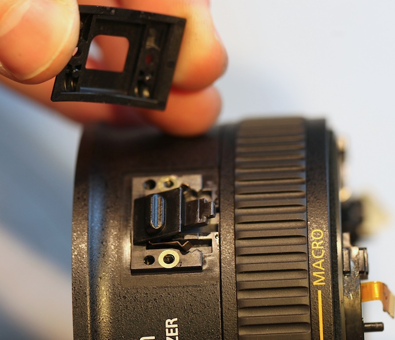
I mention it’s good that it’s accessible because I’m going to be replacing a lot of these. It probably won’t affect any of you who buy the lens, but I guarantee renters who aren’t familiar with the macro switch are going to force it (which I tested and it’s easy to do) and eventually break this little plastic tab off. That won’t have any bad effects other than letting you accidently move into macro mode, which I doubt will be a problem for anyone, really.
A few more screws and the motor – focusing assembly unit comes off. I really like how Canon is putting this as a removable unit in their newer lenses. It makes disassembly and repair much simpler. Maybe that’s one of the reasons Canon repair prices are more reasonable.
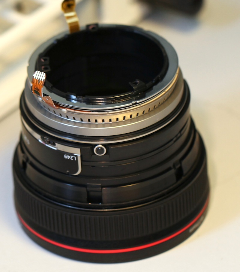
With the motor unit off the internal optical assembly containing all lens elements, helicoids, etc. is left as a group.
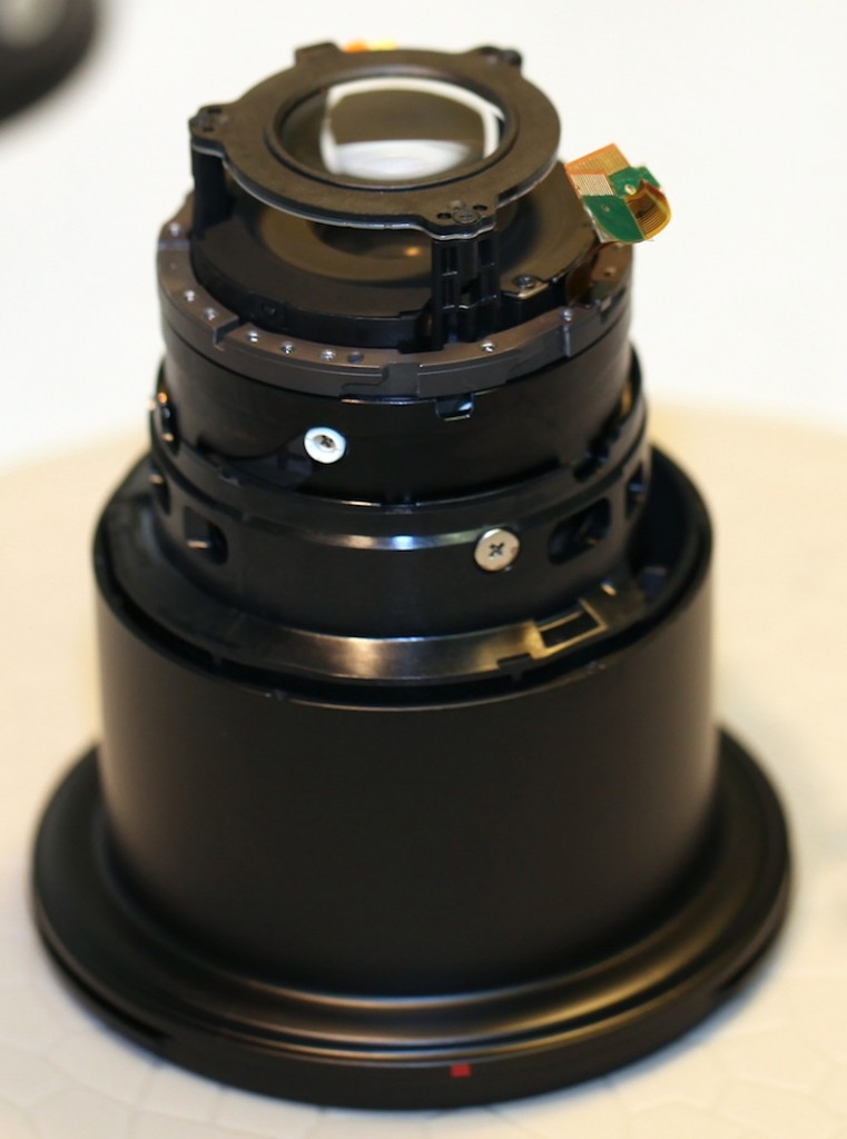
This gives us an opportunity for a clearer look at that rear element. At 24mm focal length it sits up there looking rather lonely and vulnerable.
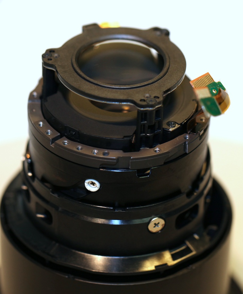
As you zoom the lens out, though, it moves forward at a brisk pace. At 70mm it’s tucked inside the barrel, right up against the next optical group.
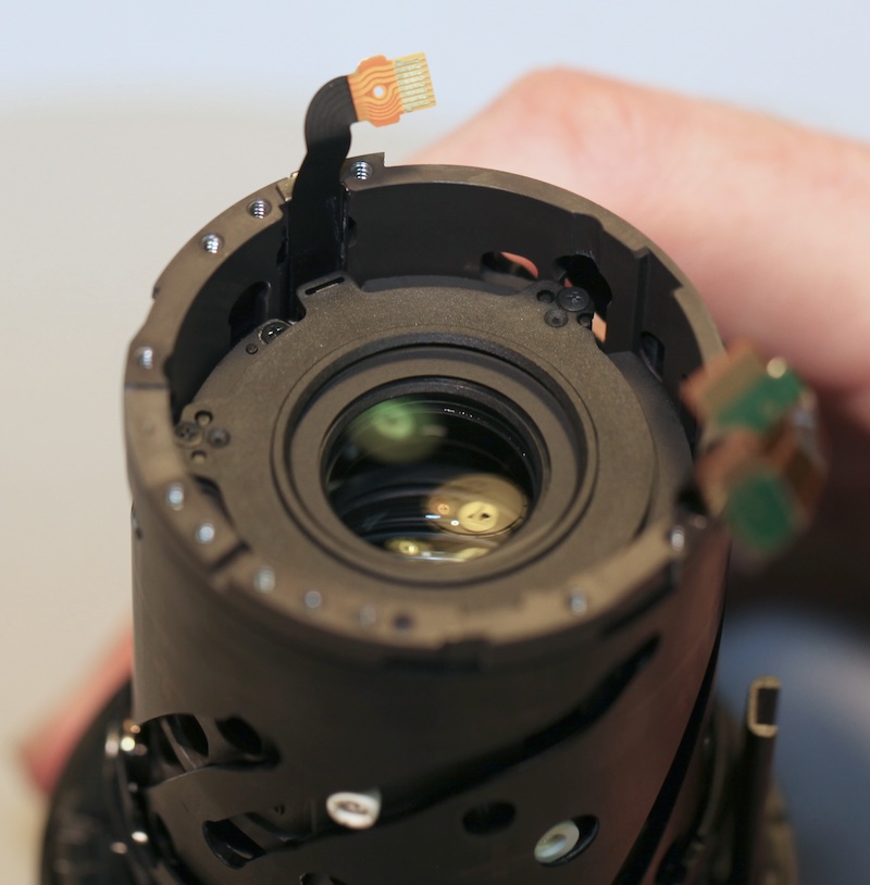
The most interesting thing is when the switch is flipped and the lens moves into macro mode, the rear element and next group move even further forward, moving as a single group.

From the outside of the optical group, you can see the very long helicoid groove that causes this large amount of travel. For those who don’t look at helicoid grooves often, they are usually simple, smooth curves. If you’re a weird photo geek, you can trace them out on paper and reproduce exactly how the elements move in relation to each other (I don’t know anyone who would bother to do weird stuff like that, of course).
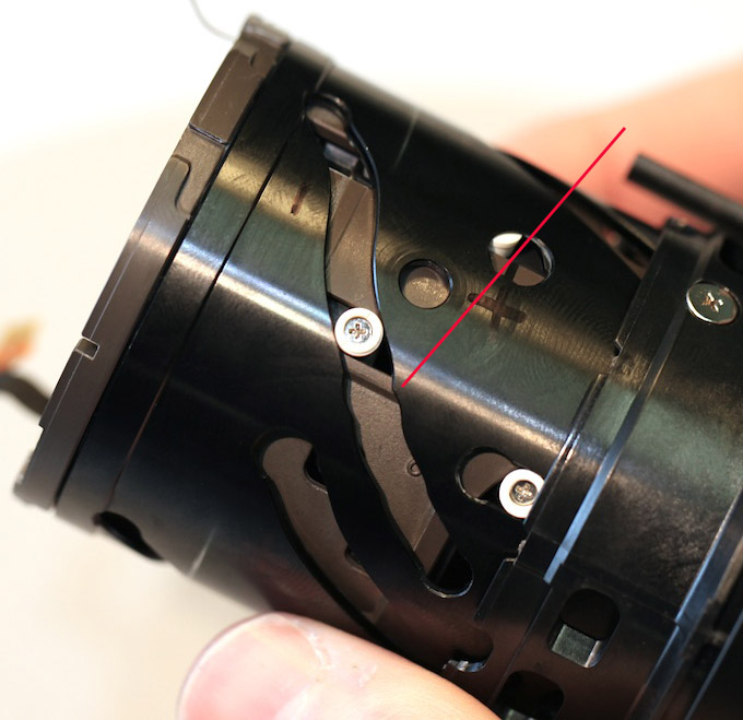
This groove is unique. I’ve never seen one like it. You can see the notch in the groove (red arrow) that begins macro mode, with a different curve above and below that notch. It shouldn’t be surprising, I guess, since in macro mode infinity focus is given up and the elements are used to bring much nearer focus than would otherwise be possible. But I’ve never seen anything quite like it. Brilliant idea and the engineering and design mathematics involved must be most formidable. I haven’t found it, but I’m certain there’s a patent out there somewhere for this. It really is like having two different lenses in one.
Finally, one of the things we tend to look at is where the lens is optically adjusted. It probably shouldn’t be surprising that such a complex lens has a complex adjustment setup. As is usual for Canon (and one of the things all PhotoGeeks love) most of the adjustments are done through oblate collars, allowing very fine tilt and centering movements, unlike the shims used in many other brands.
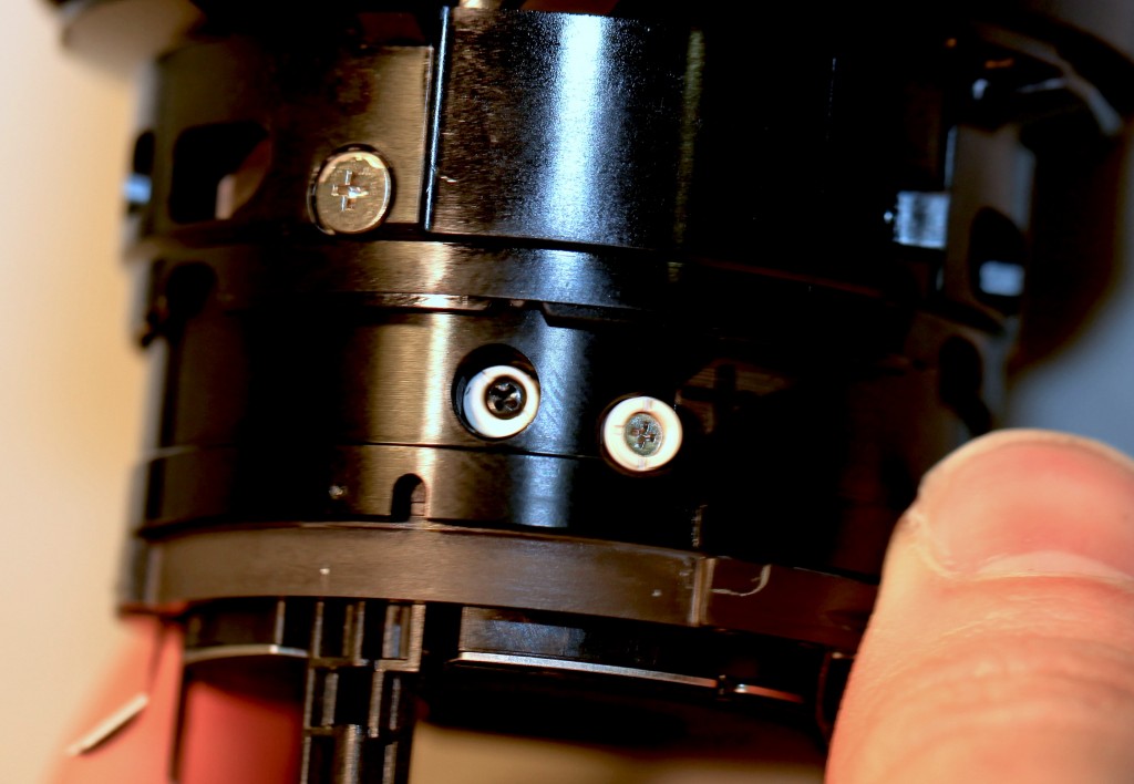
Two of the rear groups have white nylon adjustment collars. I’m pleased to note they are thick, heavy-duty collars so they should be less likely to break or wear with use. The upper (leftmost in the picture) collar is very obviously oblate so it will allow large movements, while the lower (rightmost) is a more subtle adjustment.
Deeper in the optical barrels are two forward elements that are adjusted by brass-collared screws. I’ve marked them with red arrows since they’re more difficult to see.
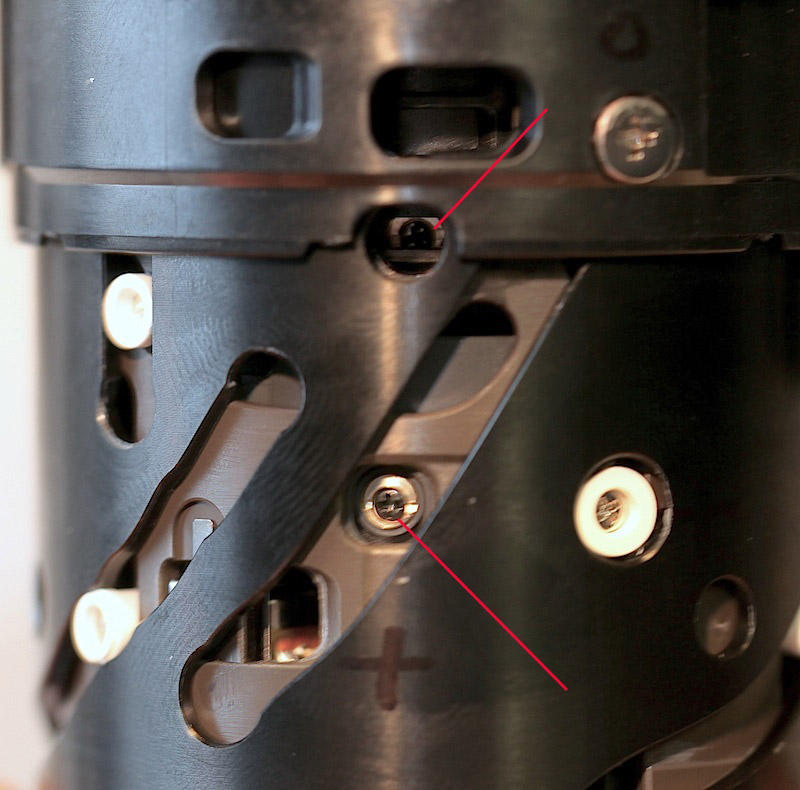
That’s at least 4 adjustable groups in this lens, which is more than most lenses have. Again, it makes sense – this is really two lenses in one. I’m guessing some of the adjustments will be largely effective at only macro ranges, while others will have more effect at normal shooting ranges.
Conclusion:
Well, this was one of our longer teardown posts and I assume we’ve lost everyone but the true geeks by now. But the Canon 24-70 f/4 IS is a truly interesting design, with some things that we’ve never seen before.
Some worry me a tiny bit. I’m certain the zoom-lock/macro switch is going to break some, although it doesn’t appear that will have any major effect.
The large number of adjustable elements is a bit concerning, too. In theory, at least, that’s more adjustments that could contribute to sample variation. On the other hand, Canon’s been a long time developing this lens and they engineer lenses more logically than anyone else. I suspect there’s a nice thick document I’ll never see that tells techs exactly which of those adjustments controls which aspects of the lens’ optics.
In some other lenses, where one element is used to adjust several variables the adjustments can be ridiculously finicky to make. It might well be that having more adjustable spots will make the adjustments more straightforward and logical, reducing sample variation. Only time will tell on that one.
Roger Cicala and Aaron Closz
Lensrentals.com
January, 2013
Author: Roger Cicala
I’m Roger and I am the founder of Lensrentals.com. Hailed as one of the optic nerds here, I enjoy shooting collimated light through 30X microscope objectives in my spare time. When I do take real pictures I like using something different: a Medium format, or Pentax K1, or a Sony RX1R.
-
Kevin Purcell
-
Todd P
-
Shimon
-
vikta
-
John R.
-
Ed M.
-
Charlie Morrison
-
Charlie Morrison
-
Pat Farrell
-
Trenton
-
Nate
-
Pete Johnson
-
KimH
-
Dr Croubie
-
Feng Chun
-
alek
-
Hasan Karagulmez
-
CarVac
-
Bart
-
Jim Harris
-
Roger Whitehead
-
Roger Whitehead
-
Mister O
-
Ralph Conway

