Geek Articles
The 8K Conundrum – When Bad Lenses Mount Good Sensors
This is a guest post from Brandon Dube, whose name you’ve seen on many of our articles. In addition to his metrology work, he also does high fidelity numerical optical simulation, and spends his summers at places like NASA/JPL working on the cameras that are going in the Mars 2020 rover.
This may be our geekiest post ever, but it’s the only way we can address some questions that a lot of people have. What is the difference between lens MTF testing (like we do on an optical bench) and system MTF testing (like almost everyone else does with a camera and lens)? How do lenses fare when sensor resolution increases?
It’s also a very long post; meant more as a reference. It’s not something you’ll sit down and read in 10 minutes.
Introduction
Today I’m going to use physical optics and simulations to show how the MTF of the lens and the MTF of the complete lens-camera system relate. After that, I’ll discuss what happens when you use ultra-high resolution video sensors with lenses of varying quality.
This post will be filled with pictures. These are scientific pictures; the prettier you think they are, the geekier you are. All of the plots in this post are made with my Python open source optics module, prysm. You can view a Jupyter notebook with all of the simulations for this post here, too.
Simulating PSFs for Different Aberrations – The Lens MTF
The Point Spread Function (PSF) shows what a single point looks like after it has passed through the lens. The “Spread” in PSF means that a point never stays a point, even with the best lenses. (In these models, diffraction is naturally included.) Measuring how much the point ‘spreads’ is basically measuring the MTF.
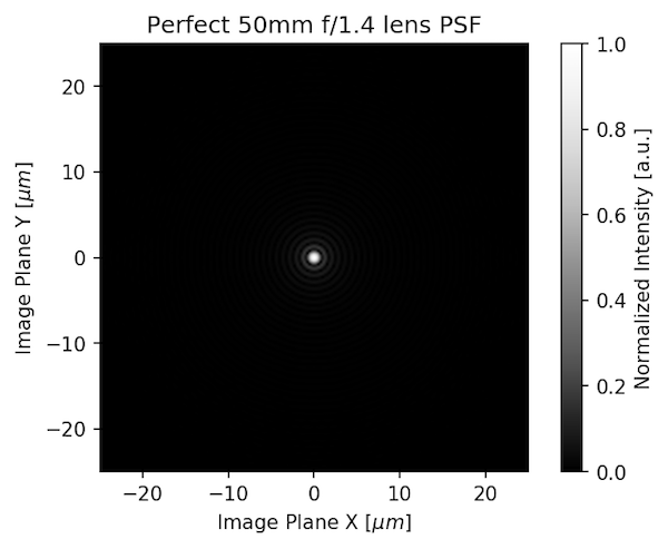
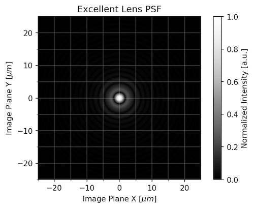
Instead of just giving you an MTF number (or PSF number), we can model different aberrations for a lens to show what the PSF looks like. First, let’s look at the PSF of a perfect lens 50mm f/1.4 lens (this exists only in theory, you can’t buy one).

That looks like a point, doesn’t it? That’s because it’s theoretically nearly perfect, which real lenses aren’t. If we add some coma to the lens, the PSF would look like this:

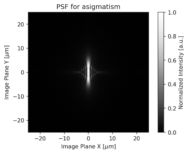
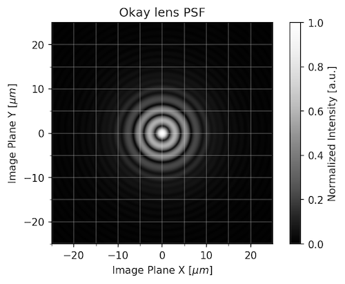
If the lens was astigmatic, the PSF would look like this:
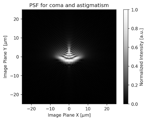
If the lens that had both coma and astigmatism, the point would look like this:
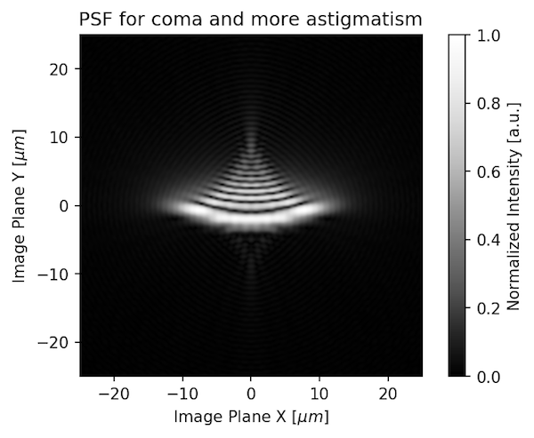
And if it had the same amount of coma and more astigmatism, it would look like this:
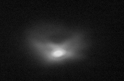
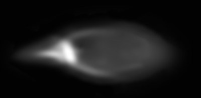
Of course a real lens has more than just 1 aberration; often about 8. A lens designer doesn’t let one aberration run out of control all by itself. Usually the aberrations balance each other. But they are always there to some degree. Here are a couple of real pinholes from fairly good lenses.
You can certainly see that the very first illustration would have the highest MTF and the others progressively lower MTF. But that’s when we measure just the lens.
Other Things Contributing to the System MTF
The system MTF is just the product of the lens MTF and sensor MTF (yes, the sensor isn’t perfect, it affects the image, too):
MTFsys = MTFlens x MTF sensor
Measurements made with Imatest, DxO, or other chart-based software give you the system MTF. In one way this is great, because it shows how the lens and camera perform together. In another way, it’s a real pain, because 2 years later when a higher resolution camera comes out you need to retest everything on the hottest new camera to see how the new lens-camera combination fares.
You can’t just assume the lens will be x amount better because the new sensor has x amount higher resolution. Two lenses may look equally great on a 24MP camera, but one might look much better than the other on a 50MP camera.
We have gone to great expense to acquire equipment that allows us to measure the MTF of just the lens without a camera. In one way this is a pain, because it doesn’t show how the lens performs on your particular camera. But, when you have tested the lens MTF in isolation, you can accurately predict the performance on any camera, as long as your data extends to a high enough spatial frequency.
The crux of this post is doing just that. It’s all simulated, but I’m good enough at simulating that NASA is trusting my models for a $3B rover on the red planet.
The Optical Low Pass Filter
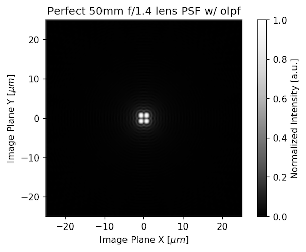
The sensor MTF has two key parts: the pixel size and the optical low pass filter (OLPF). An OLPF basically turns 1 dot of light into 4. If we take the PSF of that perfect 50mm f/1.4 lens we started with:
And convolve it (mathematically) with the OPLF, we get what the sensor is actually recording.
We tried to give you a real-world view of this by removing the OLPF from a sensor and photographing a 5 micron pinhole with and without it.
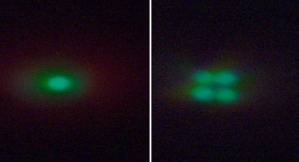
As you can see, the OLPF, just by itself, will decrease the resolution as seen by the camera compared to what the lens sends towards the camera. Some cameras have modified OLPFs, others none at all. The OLPF is necessary if the lens is “better than the sensor.” As pixels get smaller and smaller, though, it’s harder and harder to make a lens that’s better than the sensor and the OLPF is less necessary.
Pixels
The camera sensor isn’t made of round points, it’s made of little, square pixels. If we do one more mathematical convolution, introducing the pixels to the mix then we get an image that can be used to compute the system MTF.
![]()
To review, the above illustrations all showed what happens to a point of light as it passes through 1) an excellent lens, 2) the OLPF, and 3) onto the sensor and its pixels. The pinhole image from the lens (and its MTF) is a lot different than the image recorded by the camera (the system MTF).
MTF Measurements
Let’s look at how this would translate into an MTF measurement. The graph below isn’t the usual thing you see looking at one side of the lens to another. It’s evaluating how just this single point looks at different frequencies (finer details, if you will), for the lens, the lens and OLPF, and the entire system.
You can see that the MTF of the lens is spectacular (it should be, it’s theoretically perfect). The OLPF reduces the MTF mildly, and when you add the pixel (sensor) the MTF really drops. Not surprisingly, the MTF of this lens measured on an optical bench would be very different from the MTF of the lens measured as part of this system.
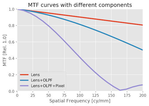
That’s for this example. The astute reader might realize that the white dot grew the most when we introduced the pixel. That’s because in this example the lens was a whole lot better than the sensor so the sensor had the most effect on system MTF. That’s not always the case.
If we have a less excellent lens, or a different sensor, things will be different. And that’s what we’ll discuss below.
So What Happens When We Change the Lens or the Camera?
OK, so we showed what happens to a point as it passes through the lens, then through the low pass filter, then as the sensor converts it to an image. Then we showed how the MTF readings changed while doing the same thing; from lens to system.
That was for a perfect theoretical lens. Now let’s look at more realistic lenses. We’re going to model a set of three lenses and five cameras and use MTF to evaluate the performance. The lens models we programmed include spherical aberration and simulation of the residuals from the polishing of the lens elements.
Let’s Meet the Three Lenses
Here are their point spread functions (the amount they blur your image) with grid overlays for 5 micron pixels:
The Best: An Excellent 85mm Lens at f/4
This excellent lens stand-in is very similar to the Zeiss Otus 85mm at f/4 in performance. In other words, one of the best lenses you can readily buy, at its best aperture.
A Good Lens: The Same 85mm Lens But Shown at f/2
This is modeled for how performance would be at f/2. Again, equivalent to one of the best lenses you can buy, but since it’s closer to its maximum aperture the point spreads more.

An OK Lens:
Finally, this model is similar to a low priced 85mm T/1.5 shot at T/1.5.
How Does This Relate to MTF (or how sharp my pictures are)?
If you take the fourier transform of those point spread functions and do some normalization, we get a computer-generated MTF for each of our three lenses. This is once again MTF vs Frequency and only the lens. Higher frequencies are important for high-resolution cameras with small pixels and no OLPF; they can image that detail. Those high frequencies are pretty irrelevant for cameras with bigger pixels (1080p) and an OLPF.
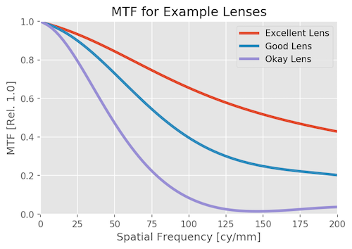
That was just the lenses, as we would test on an optical bench. Now let’s look at the system MTF; the combination of lens and camera.
We particularly want to examine how the system MTF will change for the same lens at different sensor resolutions. For this example we’re going to make some generalizations. We’ll assume a Super 35 sensor size and calculate the following pixel sizes from different resolutions.
Video resolution | Megapixels | Pixel size (microns) |
|---|---|---|
| 1080p | 2.4 | 11.6 |
| 3.4K | 5 | 7 |
| 4K | 8 | 5.8 |
| 6K | 20 | 3.8 |
| 8K | 36 | 2.9 |
System MTF with an Excellent Lens
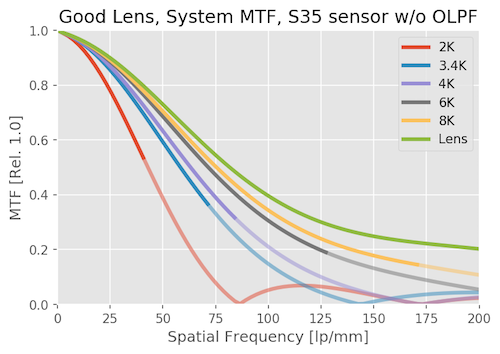
First we’ll look at how the System MTF varies with an excellent lens as you change camera resolution. We’ll do it without an OLPF first, and then look at the effects of the OPLF second.
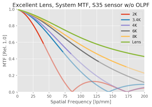
The green line is the MTF of the lens itself. The red line is what a 1080p system can resolve with this lens. In between, you see that higher resolution systems get closer and closer to the lens resolution.
The 3.4K (blue) and 4k curves have higher MTF, and extend to further frequencies than the 2K curve by quite a lot. Both are a big step up in resolution from 1080p, obviously, and 4K is only slightly higher than 3.4K as you would expect. As we continue, 6K is much better than 4K. 8K is better yet, but we’re starting to slam head-first into diminishing returns; it is improved over 6K, but not by all that much.
There’s another part of the graph that’s important; the Nyquist frequency. This is the highest frequency that can be accurately captured by the sensor. The higher the resolution of the sensor, the smaller the pixels, and the higher the Nyquist frequency. For these sensors, the Nyquist frequencies are about 43, 72, 86, 130, and 172 lp/mm, respectively. In the graph, each line becomes semitransparent beyond the Nyquist frequency for that sensor signifying the camera really couldn’t resolve that.
If the MTF is higher than 0.2 at the Nyquist frequency, then aliasing can occur. In the example above, the 1080p sensor has an MTF of nearly 0.6 at Nyquist; it is very likely to show aliasing. The higher resolution sensors have lower MTF at Nyquist and are less likely to show aliasing, although it’s still possible.
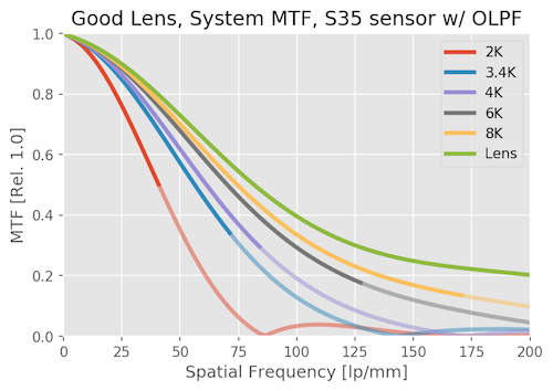
That is why OLPF filters are used. If we drop in an OLPF of “standard” strength (see e.g. Frans’ work here) it will reduce aliasing. Here’s what the same system would look like if we add an OLPF filter.
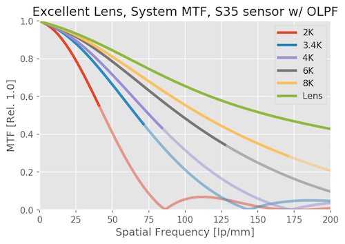
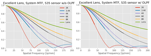
You can see that up to Nyquist for any sensor, the OLPF only reduces the MTF slightly, but beyond Nyquist it’s working to push the MTF down, making aliasing less likely. To make the comparison a little easier, I’ll compress the two graphs above so you can see them side by side. Notice how the MTF bumps, which reflect possible aliasing, are reduced. It’s most noticeable at the frequency of about 125 lp/mm in the 2k curve and out at 200 lp/mm in the 3.4K curve.
System MTF with a Good Lens
With a good lens, instead of a great lens, the MTF of the system drops significantly. Notice, though, that the 2k system really doesn’t change much; you don’t see much difference when you change from a great to a good lens at that resolution.
On the other hand, improvement in sensor resolution makes less of a difference with the good lens, especially at the highest resolutions. There’s still a big difference between 1080p and 4K, but less change between 4k and 6k, and not much change between 6K and 8K.
There is still some aliasing (look particularly around, say, 125lp/mm for the 2K sensor). It’s less severe than it was with the excellent lens, though.
The OLPF still cuts down on the aliasing, but the lens is starting to do that job for us at 3.4K and higher.
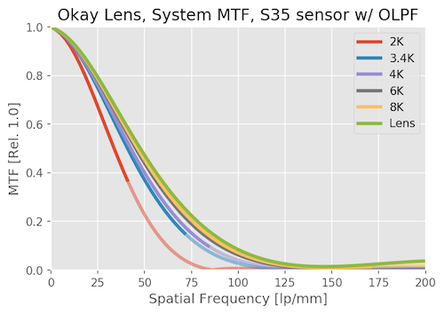
System MTF with an Adequate Lens
With just an OK lens, the resolution of the sensor makes a lot less difference than it does with a good lens. Increasing camera resolution makes far less difference in the system MTF. 6K and 8K are hardly distinguishable. Even the 2k resolution is lower than it was with a good lens.

We hardly notice the OLPF effect on this system, the lens is doing most of that job for us. Lenses that are much better than a sensor need OLPFs, lenses that are worse don’t.
So What Did We Learn So Far?
Pure lens MTF (the optical bench) shows you the upper limits of what the lens is capable of.
System MTF shows you how the whole system resolves the image.
For an exceptionally good lens stopped down a bit, then the system MTF is almost entirely dependent on the camera. Raise the resolution of the camera and the image improves dramatically.
For average and poor lenses, the system MTF is limited by the lens. Changing cameras makes only a small difference.
For most lenses the system MTF changes significantly with different sensors, but at higher resolutions a diminishing return is seen.
Optical low pass filters are necessary on low-resolution sensors, but not as necessary on high-resolution sensors. If you do see aliasing on a high resolution sensor, you can bet that lens is damned good.
There are some practical messages that are worth emphasizing.
System MTF on a low resolution sensor (1080p for example) is not a good predictor of how that lens will behave on a high resolution sensor. For video folks this means a lens that was great for 1080p may not be very good at 4k. For photo folks, don’t look at system MTF tests on lower resolution sensors.
Only the very extremes of lenses are so good or bad that you can make a blanket (blanket – from the Greek ‘blankus’ meaning clueless) statement that a lens resolves a certain number of megapixels. Yes, an Otus stopped down to f/4 will outresolve a 32 Mpix sensor, but not a lot of other lenses do. And yes, a $600, 10X zoom probably won’t resolve more than 16 megapixels even if you put in on a Canon 5Ds. But almost everything else will give a system MTF that changes to some degree with both sensor and lens.
Finally, you can use pure lens MTF values to get a good idea as to how the lens will perform at a given resolution. The rough rule is higher resolution sensors can ‘see’ higher lp/mm MTF. If you’re shooting 8k or high resolution photo, you need to look at the 40 and 50 lp/mm curves. If you’re shooting 1080p, all that matters are the 10- and 20 lp/mm curves. I’ll get into that in the addendum, but you probably want a break before tackling that.
Brandon Dube
Lensrentals.com
October, 2017
Addendum: Tracking System Performance for Each Lens
For a lot of people, the above makes sense, but you’re left wondering ‘how much will I notice that?’
Let’s look at the system performance, but instead of graphing it by MTF, let’s look at it as a function of image quality with magnification in Lightroom, Photoshop, or any other editor. To do that, we’ll look at the Nyquist frequency (the highest detail each sensor can resolve), from the full MTF vs Frequency plot.
Please pay equal attention to 25% and 50%, not just 100%. For your 8K video, how many of your viewers are watching on 8K screens with their nose touching the display? If the answer isn’t “most” and you aren’t doing a lot of cropping or have other use for the pixels, then looking at the image at 25% and 50% of full magnification is more realistic than 100%.
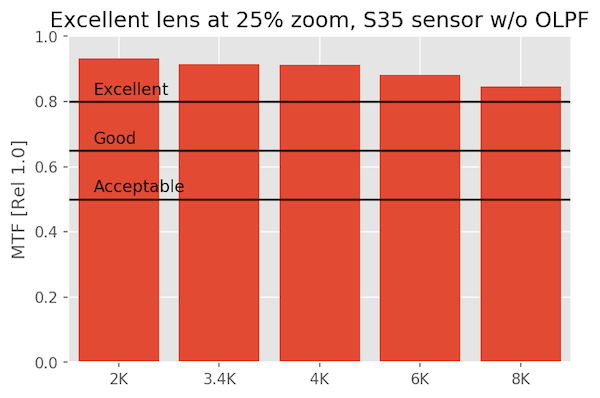
In the graphs to follow, I put a line at the MTV showing what I consider “Excellent,” “Good,” or “Acceptable” performance. My standards are quite high, and “acceptable” is not synonymous with “bad,” it’s…acceptable. You may have your own criteria that is different. You can mentally slide the cut-off bars around to what you think is right.
An Excellent Lens on Various Sensors
At 25% magnification
When we look at our excellent lens at 25% zoom, there are no surprises and it looks excellent everywhere, even on 8k video.
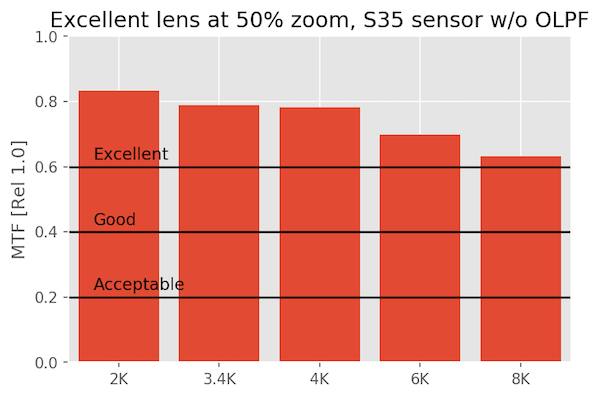
At 50% magnification
When we zoom in, things are still looking great.
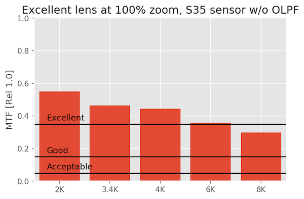
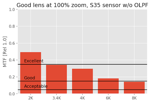
At 100% pixel-peeping magnification
Zoomed all the way in, you’re going to need an incredibly good lens to meet my standard of excellence at 8K on S35. Is 100% magnification a realistic thing to look at? Probably not unless you are cropping pretty hard. But even then the lens is almost excellent.
A Good Lens on Various Sensors
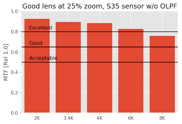
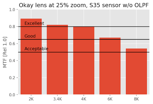
A ‘good’ lens shows some differences, particularly at 8k, but unless you’re cropping or manipulating the image so much that your doing something equivalent to 100% pixel-peeping, it’s, well, good. At 4k you won’t see much difference from 8k unless you zoom in to 100%
At 25% magnification
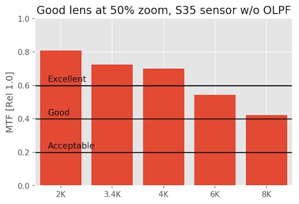
At 50% magnification
At 100% magnification
An OK Lens on Various Sensors
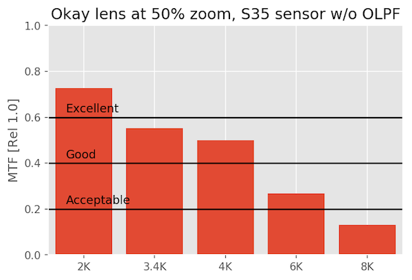
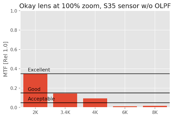
The okay lens just isn’t made for this kind of scrutiny, and fails to even be excellent at 6K or 8K. But it’s perfectly acceptable at 1080p and 4k. It’s rather a waste on an 8k sensor.
At 25% magnification
At 50% magnification
At 100% magnification
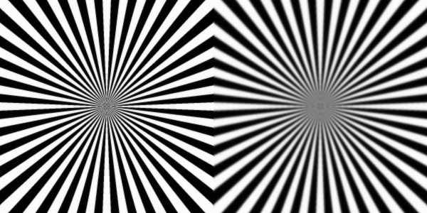
One Last Picture
Since you may be more used to this, here is what our excellent (left) and OK (right) lenses would look like if you took a Seimens Star chart image at 8k and 100% magnification. If you did it on a 1080p camera, they’d be nearly identical.
So What Else Did We Learn Today?
We used physical optics to model the performance of lenses, and examples of lenses on different Super 35 video camera sensors. We saw that an “okay” lens works great at 2K, and is pretty good at 4K, but it does not so work well at 8K. A “good” lens might hold up pretty well at 8K, at least in the middle of the frame. We also saw that an “excellent” lens is still not perfect when put in front of an 8K, Super 35 sensor at high magnification.
This implies that maybe 8K can be wasted, or at least the limit, for a Super 35 sensor size. You may need a VistaVision or larger sensor to really capture that kind of resolution unless you’re shooting with an excellent lens stopped down a bit. Of course, there may be very real reasons to use 8k other than absolute resolution. And even if the image is a little soft at 100%, is that such a terrible thing?
Author: Brandon Dube
I’m Brandon, a co-founder of Olaf Optical Testing, and the brains behind a bunch of the MTF and other tests you see on this blog. I got into the whole optics thing because I wanted to make my own camera lenses someday.
-
SolJuJo
-
Brandon Dube
-
HF
-
SolJuJo
-
Brandon Dube
-
Max
-
Ummon
-
Ummon
-
Roger Cicala
-
Ummon
-
David Bateman
-
Brandon Dube
-
Brandon Dube
-
Brandon Dube
-
Matt Grum
-
Matt Grum
-
SIMONE PIETRO SARAGOSA
-
alek_komarnitsky
-
Brandon Dube
-
Brandon Dube
-
Brandon Dube
-
Brandon Dube
-
Brandon Dube
-
SIMONE PIETRO SARAGOSA
-
Frans van den Bergh
-
Matt Grum
-
Frank Neulichedl
-
bokesan
-
geekyrocketguy
-
Ed Hassell
