Just MTF Charts
Just MTF Charts: Perspective Control Lenses
I had a little hesitation about whether we should post these. Most people considering a tilt-shift aren’t thinking ‘I want the absolute best sharpness.” Plus what we show is the MTF without the lens tilted or shifted, both of which will affect the resolution to some degree, but you’re probably using them tilted and shifted. And finally, because tilt-shifts aren’t mainstream we don’t have 10-copy data for most. Generally, we have 5 or 7 copies tested, although we do have 10 copies for most of the Canon brand.
On the other hand, there really is no resolution data out there for Tilt-shift lenses, and no MTF charts. So I’m going to go ahead and post what we have.
Again, this is MTF with the lens in ‘straight-up’ position, neither tilted nor shifted. Some playing around we did with a few lenses shows the MTF drops pretty significantly with significant tilting or shifting. Also remember, with these lenses we’re comparing some designed 30 years ago with some designed in the last few years. The difference is pretty apparent.
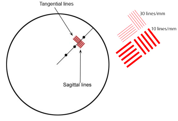
A Quick How to on Reading MTF ChartsIf you’re new here, you’ll see we have a scientific methodology to our approach, and use MTF charts to measure lens resolution and sharpness. All of our MTF charts test ten of the same lenses, and then we average out the results. MTF (or (or Modulation Transfer Function) Charts measure the optical potential of a lens by plotting the contrast and resolution of the lens from the center to the outer corners of the frame. An MTF chart has two axis, the y-axis (vertical) and the x-axis (horizontal). The y-axis (vertical) measures how accurately the lens reproduces the object (sharpness), where 1.0 would be the theoretical “perfect lens”. The x-axis (horizontal) measures the distance from the center of a lens to the edges (measured in millimeters where 0mm represents the center, and 20mm represents the corner point). Generally, a lens has the greatest theoretical sharpness in the center, with the sharpness being reduced in the corners. Tangential & Sagittal LinesThe graph then plots two sets of five different ranges. These sets are broken down into Tangential lines (solid lines on our graphs) and Sagittal (dotted lines on our graphs). Sagittal lines are a pattern where the lines are oriented parallel to a line through the center of the image. Tangential (or Meridonial) lines are tested where the lines are aligned perpendicular to a line through the center of the image.
From there, the Sagittal and Tangential tests are done in 5 sets, started at 10 lines per millimeter (lp/mm), all the way up to 50 lines per millimeter (lp/mm). To put this in layman’s terms, the higher lp/mm measure how well the lens resolves fine detail. So, higher MTF is better than lower, and less separation of the sagittal and tangential lines are better than a lot of separation. Please keep in mind this is a simple introduction to MTF charts, for a more scientific explanation, feel free to read this article. |
Canon Tilt-Shift Lenses
Canon TS-E 17mm f4L
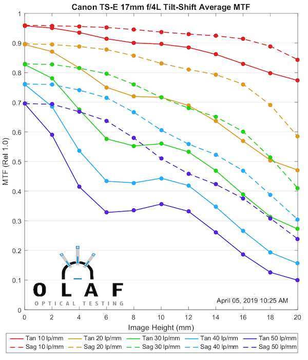
Lensrentals.com, 2019
Canon TS-E 24mm f3.5L II
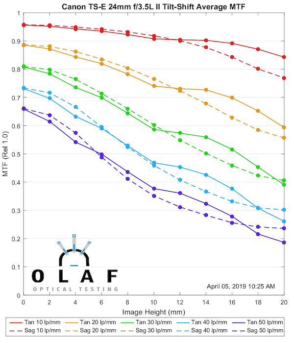
Lensrentals.com, 2019
Canon TS-E 45mm f2.8
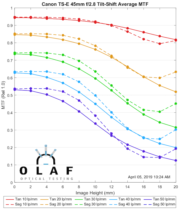
Lensrentals.com, 2019
Canon TS-E 50mm f2.8L Macro

Lensrentals.com, 2019
Canon TS-E 90mm f2.8
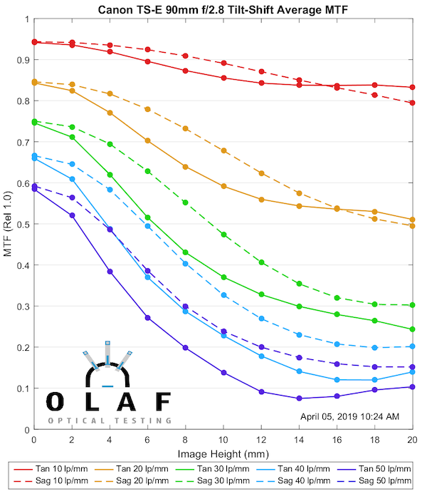
Lensrentals.com, 2019
Canon TS-E 90mm f2.8L Macro
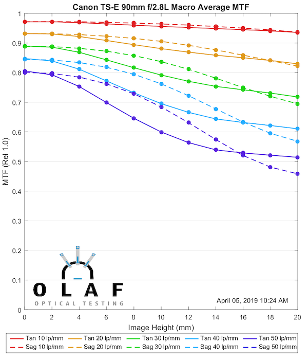
Lensrentals.com, 2019
Canon TS-E 135mm f4L
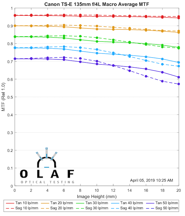
Lensrentals.com, 2019
Nikon PC-E Lenses
PC-E Nikkor 19mm f4E ED
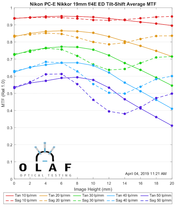
Lensrentals.com, 2019
PC-E Nikkor 24mm f3.5 ED
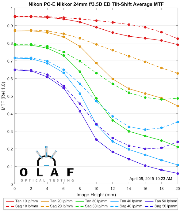
Lensrentals.com, 2019
Nikon PC-E 45mm f2.8 ED
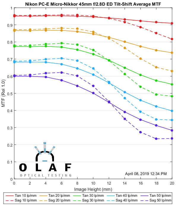
Lensrentals.com, 2019
PC-E Micro-Nikkor 85mm f2.8D
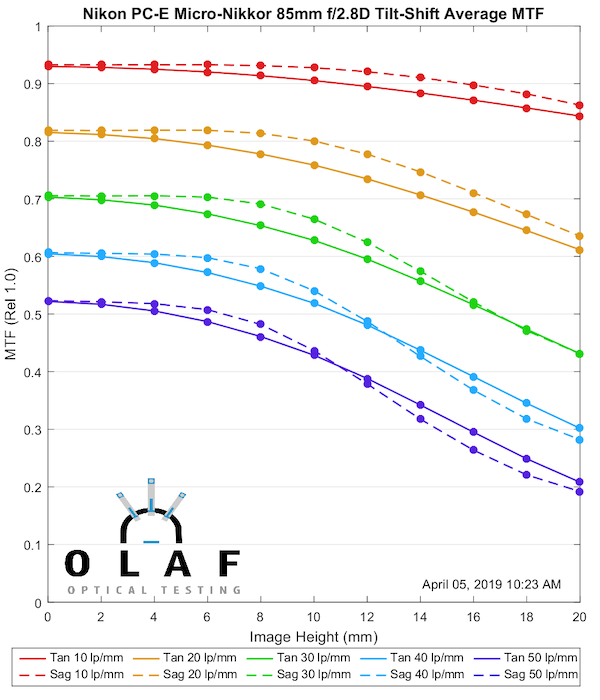
Lensrentals.com, 2019
Schneider Super-Angulon and Makro-Symmar
Schneider 28mm f2.8 Super Angulon
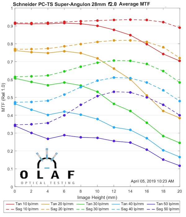
Lensrentals.com, 2019
Schneider 50mm f2.8 TS Super Angulon
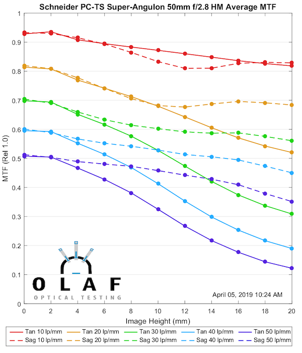
Lensrentals.com, 2019
Schneider 90mm f4.5 Makro-Symmar
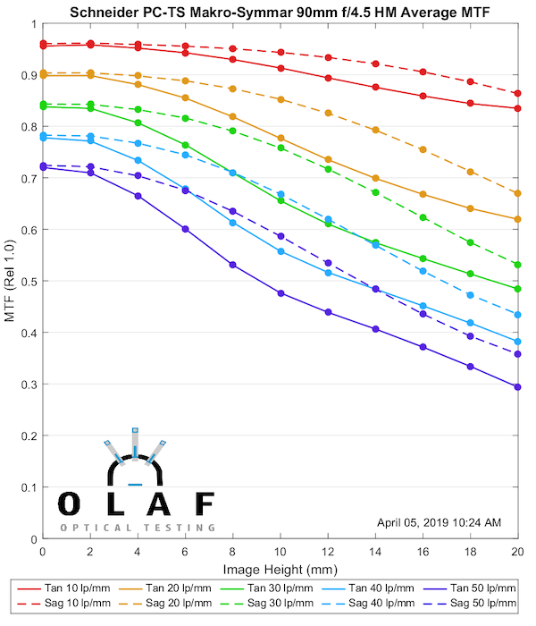
Lensrentals.com, 2019
Rokinon
Rokinon-Samyang 24mm f3.5 TS
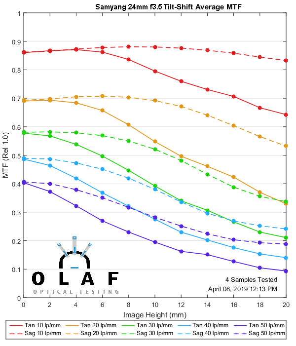
Lensrentals.com, 2019
Roger Cicala, Aaron Closz, and Brandon Dube
Lensrentals.com
April, 2019
Addendum: The Digital Picture is hosting the MTF charts on their comparison tool, putting them up as we publish them here. It’s a great way to compare two lenses for the one or two of you who like to do that. The Canon and Zeiss primes are already up, the Sigma should be added by tomorrow.
Author: Roger Cicala
I’m Roger and I am the founder of Lensrentals.com. Hailed as one of the optic nerds here, I enjoy shooting collimated light through 30X microscope objectives in my spare time. When I do take real pictures I like using something different: a Medium format, or Pentax K1, or a Sony RX1R.
-
Samuel Chia
-
Brandon Dube
-
Samuel Chia
-
Samuel Chia
-
Andreas Werle
-
Andreas Werle
-
Andreas Werle
-
Brandon Dube
-
Brandon Dube
-
Samuel Chia
-
Roger Cicala
-
Samuel Chia
-
Samuel Chia
-
Michael Tiemann
-
hendrik
-
lwestfall
-
Kers
-
Roger Cicala
-
Max Manzan
-
Franz Graphstill
-
Roger Cicala
-
Roger Cicala
-
Roger Cicala
-
Roger Cicala
-
Daniel Eggerstorfer
-
Alan
-
Lee
-
lwestfall
-
Andreas Werle
-
l_d_allan
