We’ve been impressed with most of the lenses that have come out for the L mount cameras but haven’t taken many of them apart. But as luck would have it, we have several Panasonic Lumix Pro 70-200mm f/4 OIS lenses needing repairs for autofocus issues. In the U. S., Panasonic doesn’t offer repair really, just an exchange program.
Exchange is fine, but it’s also a slow and somewhat unpredictable process. We much prefer fixing things in-house in a day or two, rather than having the item out of stock during a 6-week exchange process. And, in a bit of foreshadowing, we’ve found some linear AF systems are a bit fragile, but also easily repaired. So we decided to take a look inside to see if we could figure out what was broken.
The Panasonic Lumix S Pro 70-200mm f4 OIS
This is a 2.17lb, 7-inch long (985g, 179mm) internally zooming lens. It’s made up of 23 elements in 17 groups with an asphere, one ultra-high refractive element, and in one of the more interesting bits of official marketing copy, it has ‘one extra-low dispersion element and three extra-low dispersion elements’. I guess that means there are four ELD elements (probably one is extra extra) and that Panasonic should have someone proofread their advertising copy.
It has a main linear focusing motor with a secondary stepper motor and a 5-stop OIS stabilizer. It is advertised as weather-sealed, which is, of course, always a lie, but usually does mean weather-resistant. It is reasonably priced at about $1,650.00; a bit more than the older Sony FE 70-200 f/4, a bit less than the Canon RF 70-200 f/4.
Online reviews are almost universally positive, which I trust. Several online reviewers also commented on its excellent build quality, which I don’t trust. Because, you know, build quality is inside and reviewers look at the outside. Stay in your own lanes, guys. So, let’s look at the inside today, shall we?
Well, How Do We Get There?
With all lenses we haven’t disassembled before, there’s always the ‘which way is best to go in’ question. We generally answer this question by starting the wrong way and then changing direction, as we will here. Twice.
We know we can always get the bayonet off, so we started there.
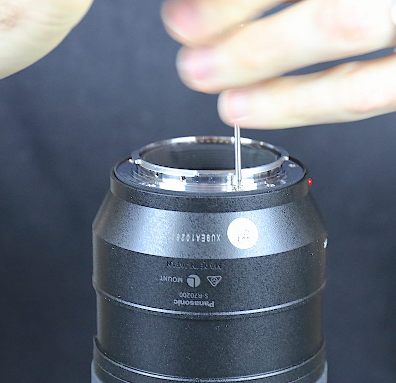
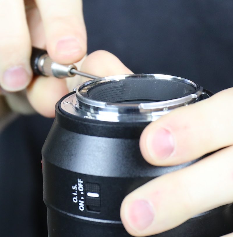
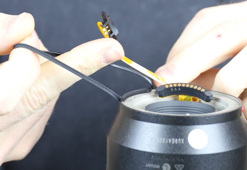
We take the bayonet and plastic rear baffle off, leaving the electrical connections behind for now.
Given this is a weather-resistant lens, there’s a nice rubber gasket back there, too, as you would expect.
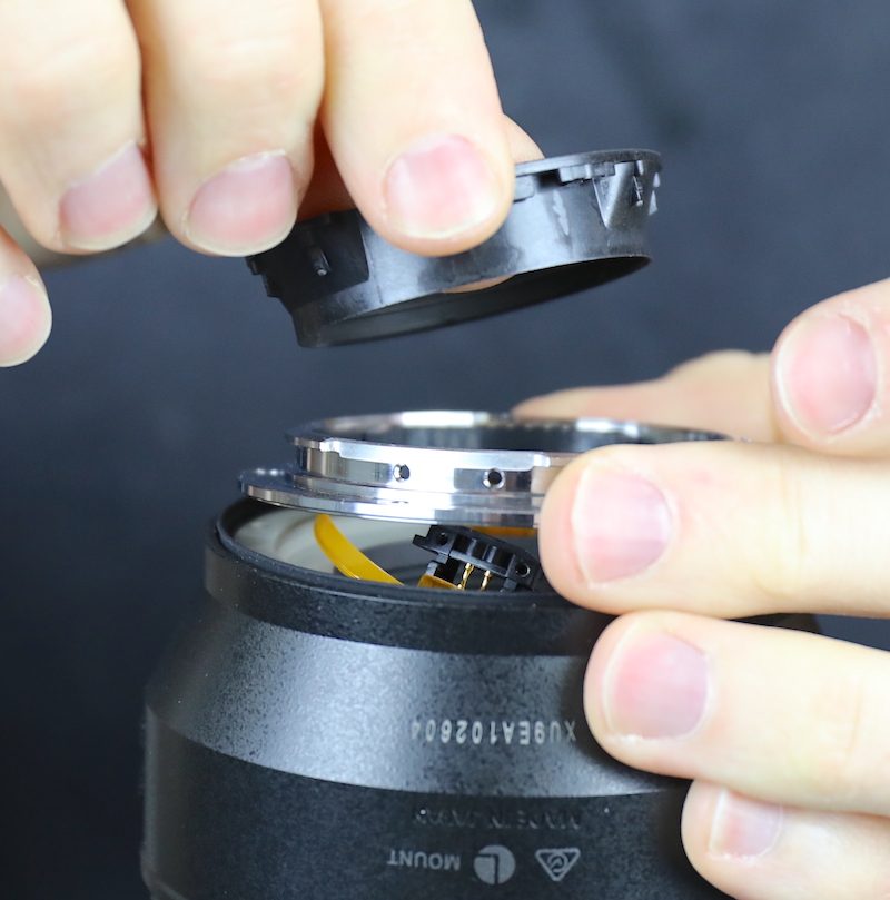
Removing a few more screws lets us take off the rear barrel.
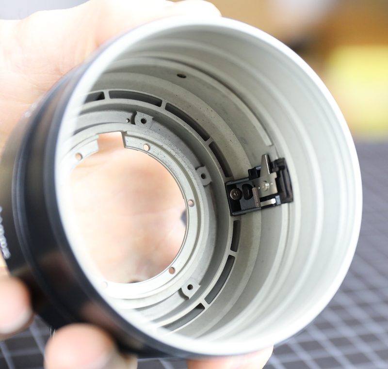
Nothing really in the rear barrel other than a mechanical off-on switch for the IS unit.
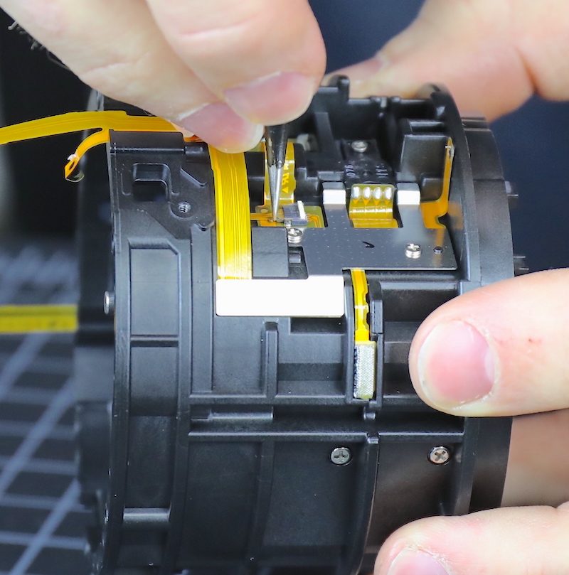
Looking at the inner lens below, the forceps are pointing to the electrical IS switch that the mechanical switch on the barrel activates. You can also see the engineers who designed this lens never use one straight flex cable when they could use two bent and curved ones.
There’s a heavy-duty ground wire from the circuit board, which isn’t unusual. But there’s a second ground on the other side, which is different. I doubt it’s going to influence anyone’s purchasing decision, but rest assured, the circuit board is thoroughly grounded.
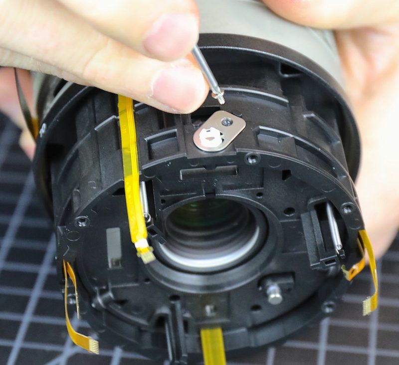
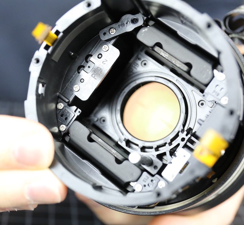
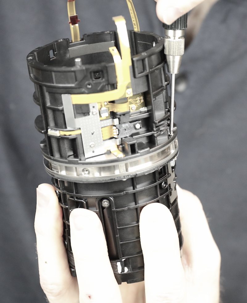
OK, here’s the other ground wire (not interesting), slightly to its left are the OIS position sensors (maybe a little interesting), and further to the left, the brown flex connector from what we will later refer to as the Sensor of Unusual Type and Unknown Function (SUTUS).
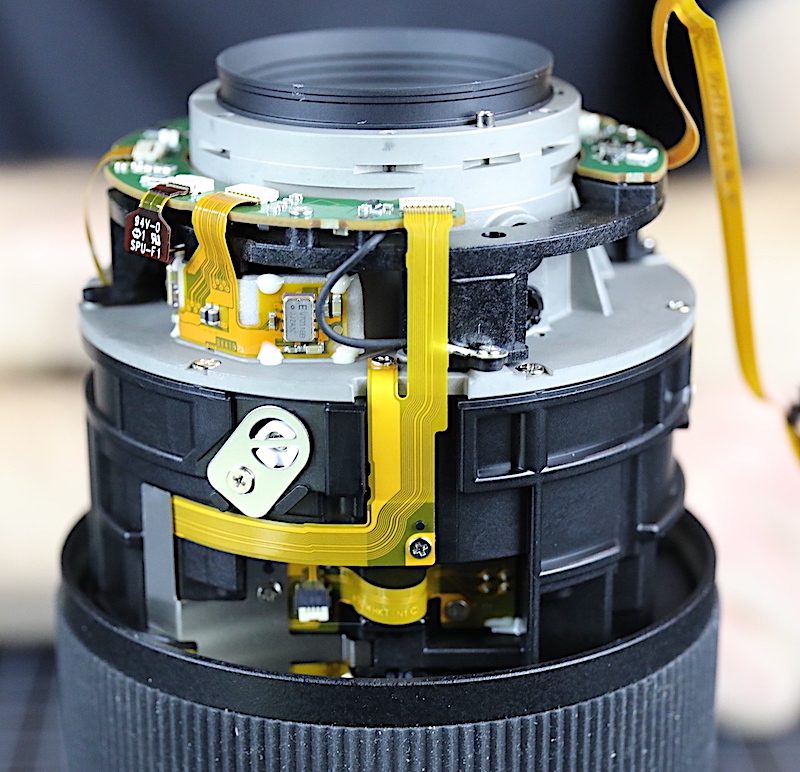
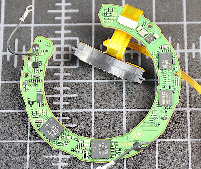
The PCB came off after unhooking a bunch of flexes, and looks pretty much like most PCBs.
This gives us a nice look at a pair of springs poking up from the OIS unit. There are two of these 120 degrees apart; the SUTUS is in the third 120-degree position.
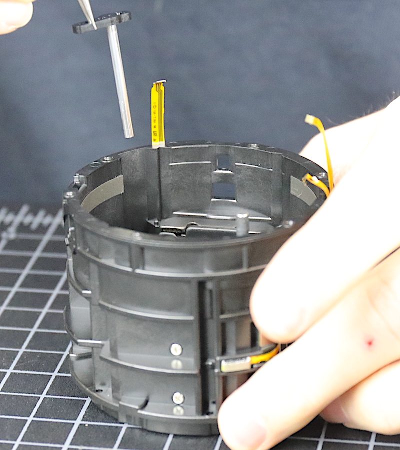
And now we do our usual pause to look at things with the rear barrel off and decide what to do next.
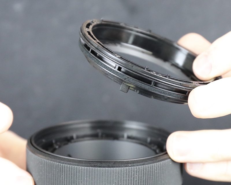
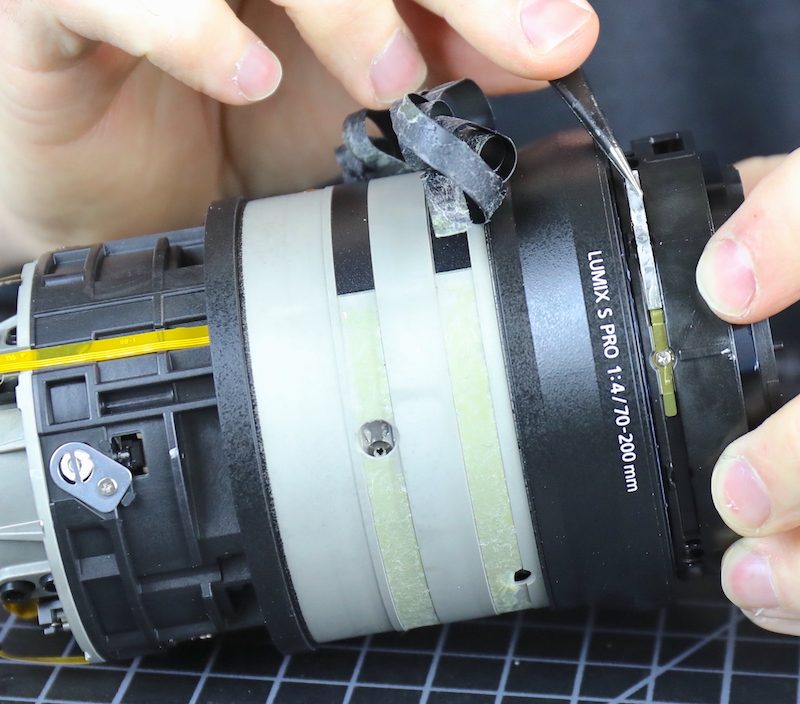
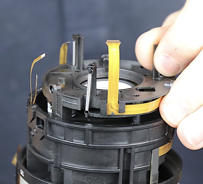
There are two nice, robust pieces of sealing tape on the zoom ring, which usually means there are screws and keys holding the ring on underneath.
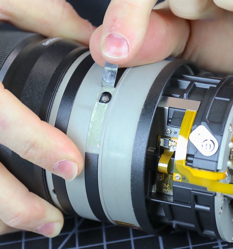
In addition to the screws, there’s a position sensing brush on the zoom ring. This is over a magnetic, rather than electronic, ribbon.
With all of the screws and key removed we next, well, did nothing. Despite everything removed, the zoom ring didn’t budge. So, using our powers of deduction, and seeing that the zoom ring wasn’t going to slide off the back, we headed for the front of the lens.
Disassembling the Front Portion
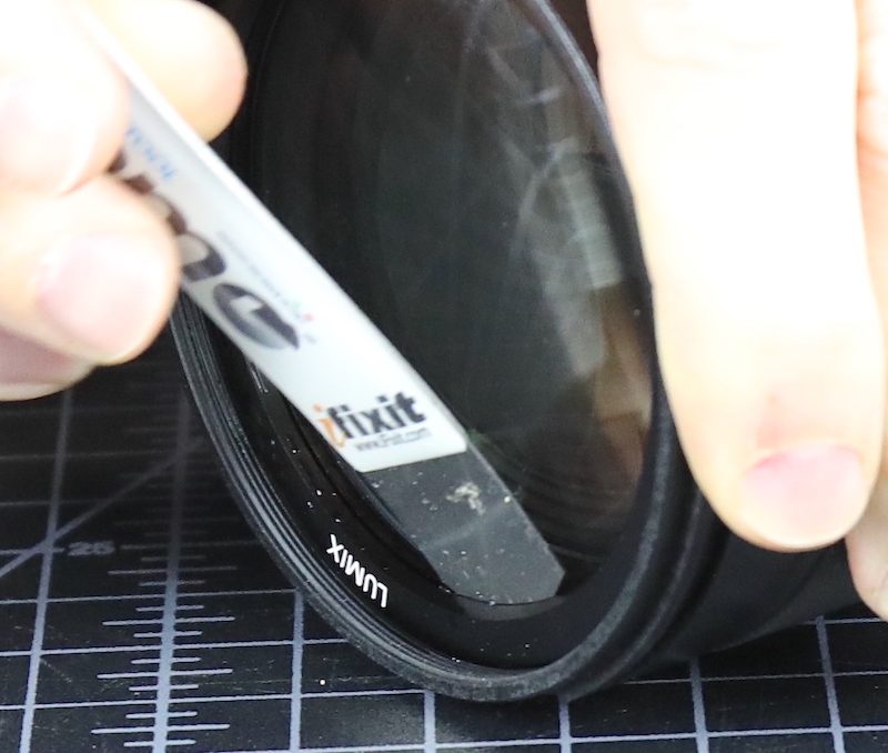
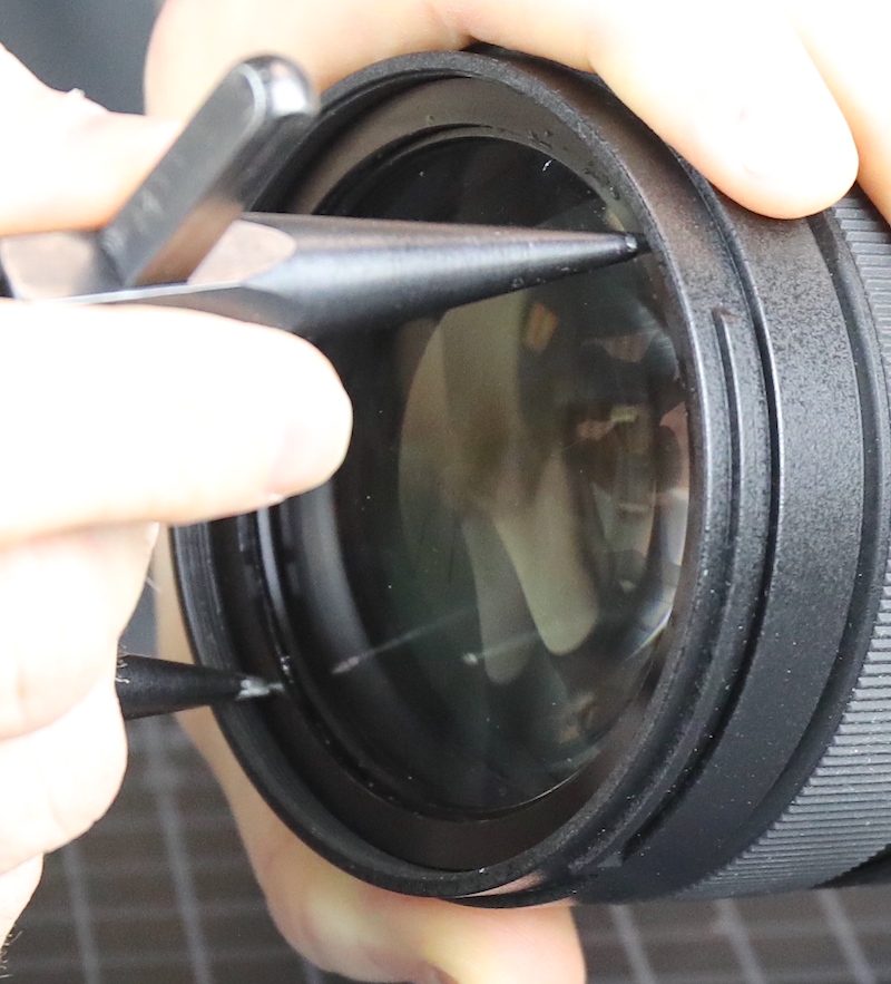
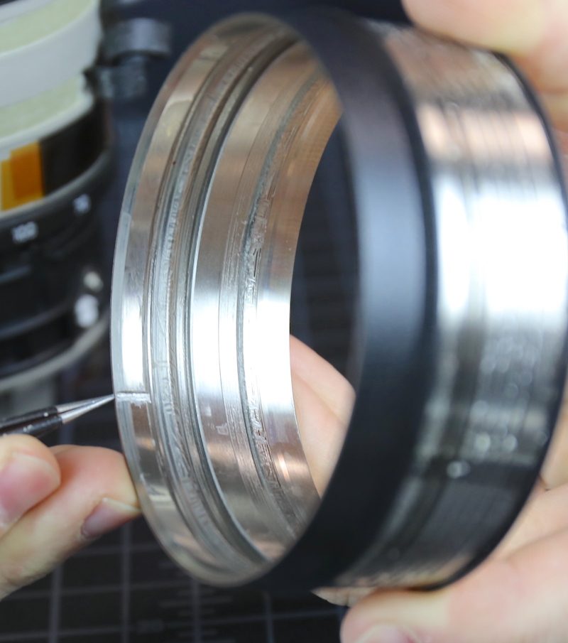
Panasonic lenses in general have makeup rings that are difficult to remove. So alcohol, heat, and vigorous use of a spudger were needed.
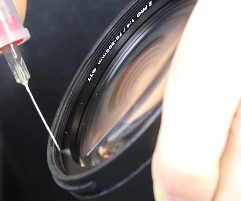
For those of you who want to know how you use a metal spudger without scratching glass, the answer is experience. How do you get experience? You scratch some glass.
In belt and suspenders fashion, there’s a spanner ring under the makeup ring.
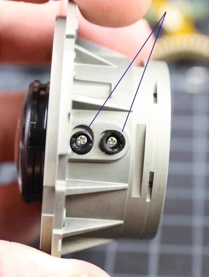
With the spanner ring removed, we finally have access to the 6 screws holding the front ring on. I have zero fears that the front ring is ever coming off by accident. (The paired screws are holding the front element in place.) You can see there’s some sealing foam around the edge of the front element and another around the edge of the barrel ring, helping provide a dust and moisture seal against the makeup ring and spanner ring we just removed.
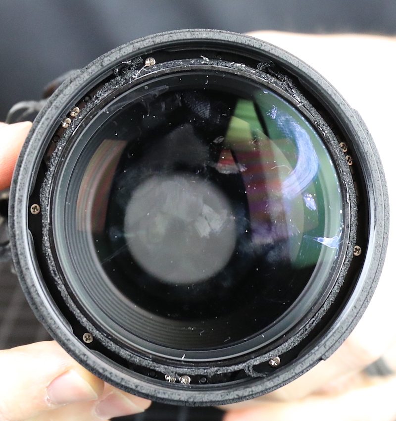
The outer ring comes off easily and we can now see there are no shims under the front group screws, so we take out the front group.
The focusing clutch comes out in several rings. There’s has another dust-seal foam ring; this is a well-sealed front area. (That still doesn’t make it waterproof, but it’s a good job.)
The manual aperture ring has some friction spring tabs.
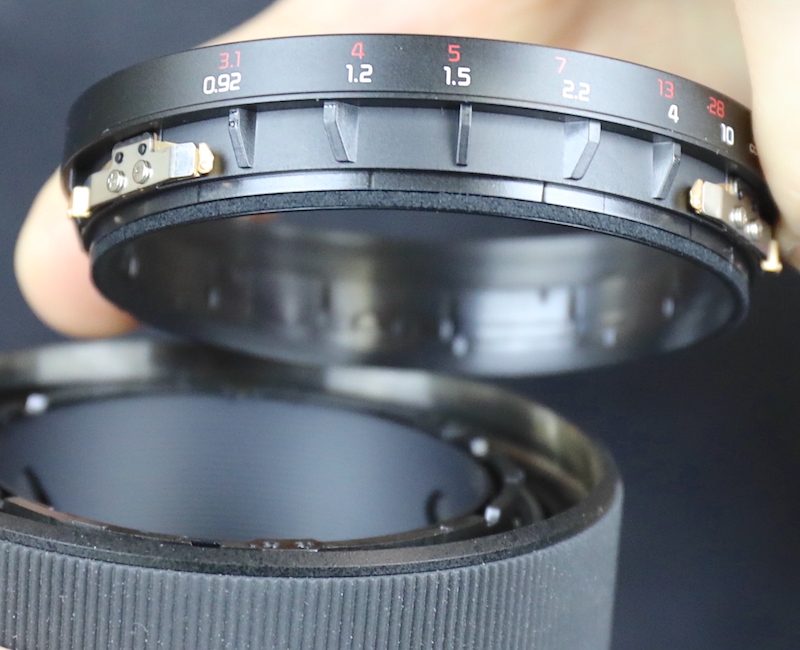
Next, we take the focusing ring rubber off and remove another spanner ring so we can start disassembling the focusing clutch.
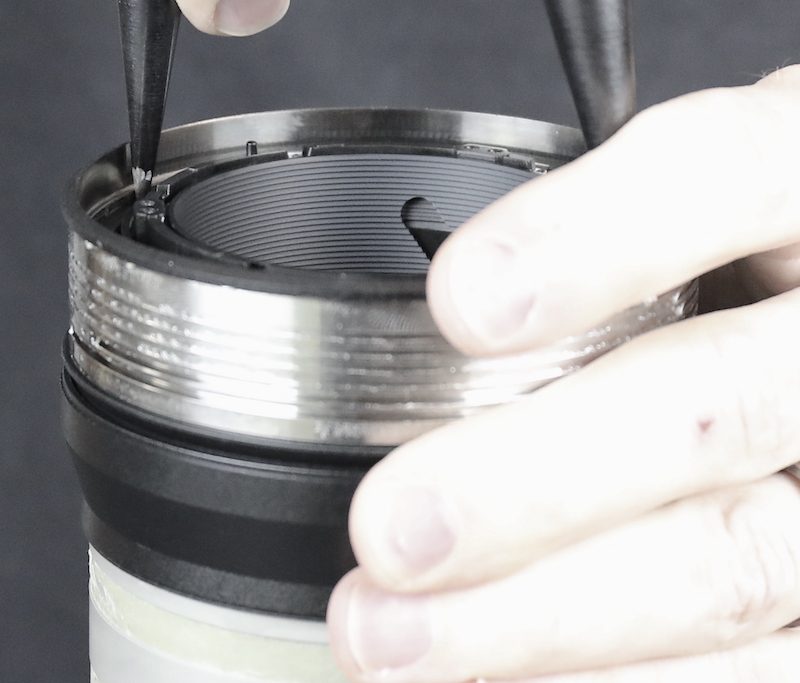
Then we got to do that chore we hate most; find the surprise ball bearings that came flying out when we removed the focusing ring. Ball bearings and springs always make disassembly interesting.
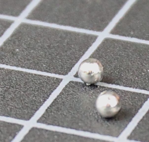
Turns out the ball bearings fit in slots and serve as rollers when the clutch is moved back and forth to change from auto to manual focus.
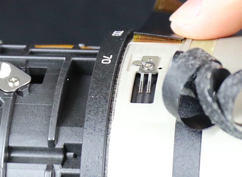
There are a few more flat, tensioning springs to take out. And then a ring holding a second position sensor brush.
After which we took a few minutes to look around, decided we’d come to another dead end, and went … .
Back to the Back
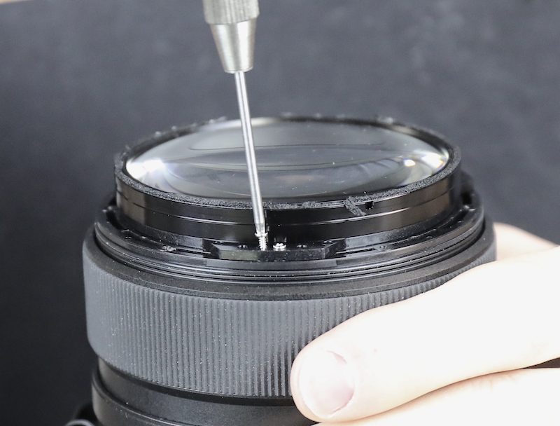
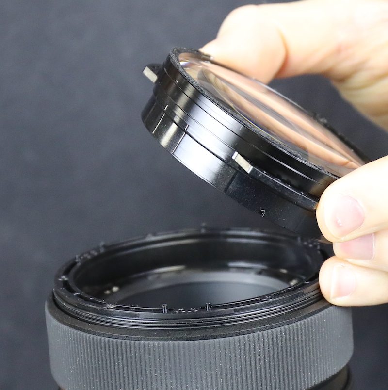
The rear group, after you get all the flexes out of various slots, comes off by removing a few screws. Taking this off isn’t going to get the zoom ring off, but might give us a better look inside.
We’re glad it’s a self-contained group because there are several eccentric adjustment collars for this group. So it’s nice to just leave all that alone.
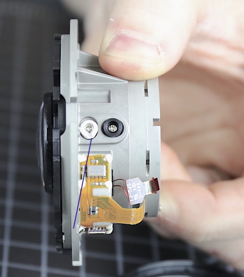
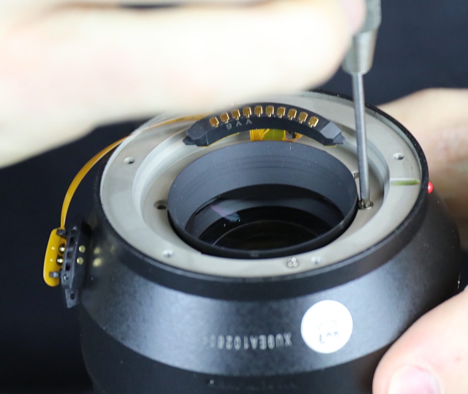
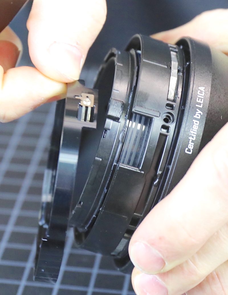
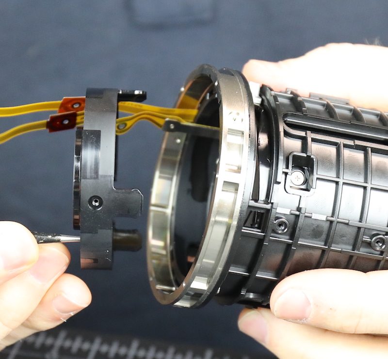
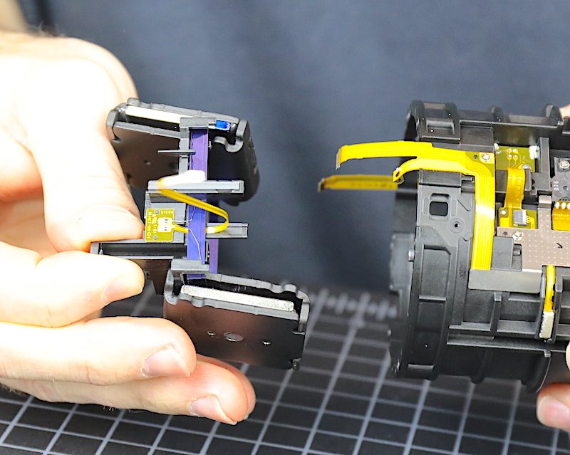
Now that we have this out we can examine the Unknown Sensor of Unusual Size. The bottom end sits on top of this sort of translucent window in a ring that seems held to the rear group by 6 more screws.
Take the screws out and we can take that assembly off of the rear group. Honestly, flex cable soldered to wire is, well, unusual. Have we seen that before? Yes. In the last decade? Not so much. It kind of suggests this is an off-the-shelf part adapted to a lens. That’s not a bad thing, just a thing.
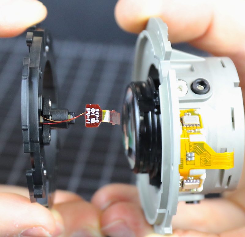
You can see in the above picture the SUTUS is encased in a plastic cover that screws down to the rest of the assembly so we took that off, of course.
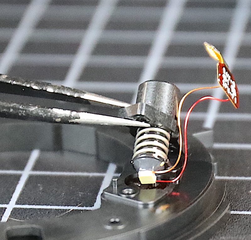
At first, we thought that was an electric coil, but with the plastic cover removed, it becomes apparent that’s a spring.
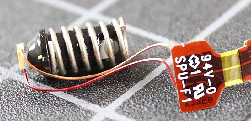
The base that sits over the thin window is where the wires enter. Up at the top (closest to the mount) is a sensor or window. It looks rather like an LED, but that makes no sense. Could be an odd piezo motor but it’s not able to move anything. That would make it a MUTUS instead of a SUTUS, but we don’t think that’s the answer. Magnetic field sensor maybe? That’s our best guess, but we really have no clue. Hopefully, someone will tell us in the comments.
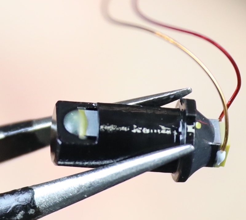
But we’re here about an AF motor not working and we can’t figure out any way this is affecting the AF system. Or if it is, we sure can’t fix it since we don’t know what it is. Although if unplugging it and plugging it back in might work, we’re certainly doing that.
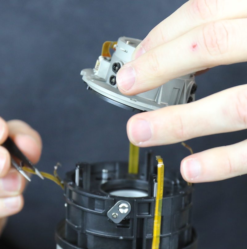
Back to What We Came Here for
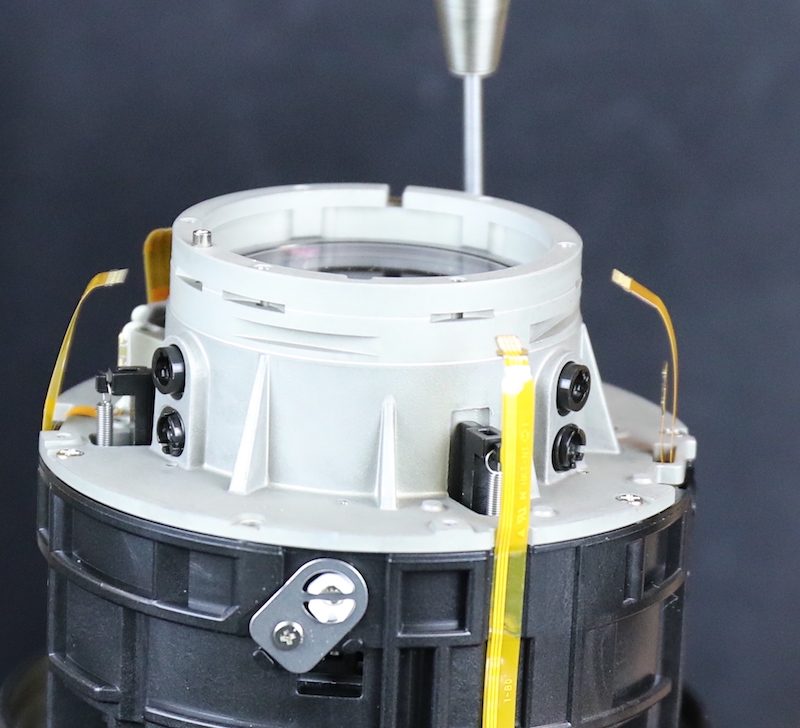
The next element is the OIS unit. It’s held in place by another method we haven’t seen before; some thick nylon eccentric pegs held in place by a metal bracket. The nylon pegs are able to adjust tilt in the OIS unit, but only as a gross adjustment. Because of the metal cross bracket, they can only be turned in 90-degree increments. Still, this seems a nice design, giving both optical adjustment capability and also some shock-absorbing ability.
With those removed, the OIS unit lifts out as an assembly.
Underneath you see the electromagnets and the optical element of the OIS.
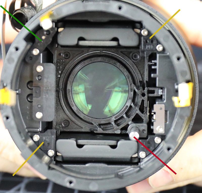
With the OIS unit removed we can see the focusing elements and linear focusing motor. The mount for the focusing group is square. You can see the larger main sliding rod (red arrow) and the cover of the secondary sliding rod (green arrow). The other two corners of the focusing group fit into plastic corners (yellow arrows) to prevent any tilt with movement and both have soft rubber bumpers to minimize shock at the end of the focus group’s travel. You can see the tops of the two magnets at the top and bottom of the focusing assembly.
This angled view shows how far forward the focusing group can move forward. You can see the upper stop plate (upper left in the picture) and the two corner bumpers (one in focus on the left next to Aaron’s finger, the other out of focus opposite it). Removing all of those and the secondary rod should let us slide the motor out.
With all these parts off of the rear, we were able to get to some screws under the front barrel that had not been accessible. So we’ll do that before we mess with the focusing motor anymore.
With those those gone, first the inner front barrel,
and then the zoom ring, can be removed.
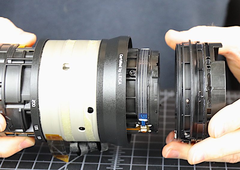
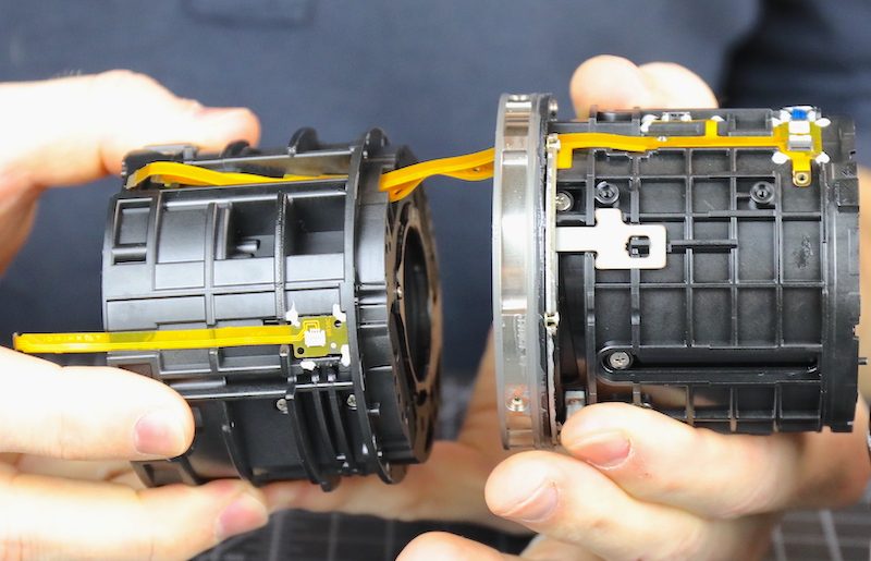
Now we’re down to the inner core of the lens. The front and rear elements, along with the OIS unit are gone, but there’s still a lot of stuff (including another 14 lens elements) in here.
Like most 70-200mm lenses, you can see this lens is two parts joined at the center by a metal connecting ring. Let me take a moment to say “well done” to Panasonic. That’s a thick piece of metal in proportion to the size of the two halves. It’s not a flat, easily bendable plate.
They wouldn’t put screws up in there if they didn’t want us to take it apart, right? Separating the halves will give us better access to the linear focusing motor which is why we came.
When the two halves come apart you can see that the front half actually inserts into the connecting ring; it’s not just attached to it by screws. This provides another method of strengthening the joint, which, we appreciate. Some 70-200mm lenses just screw each half into a weak flat plate. Some lenses that do that have the unfortunate tendency to break in half, which is always disappointing.
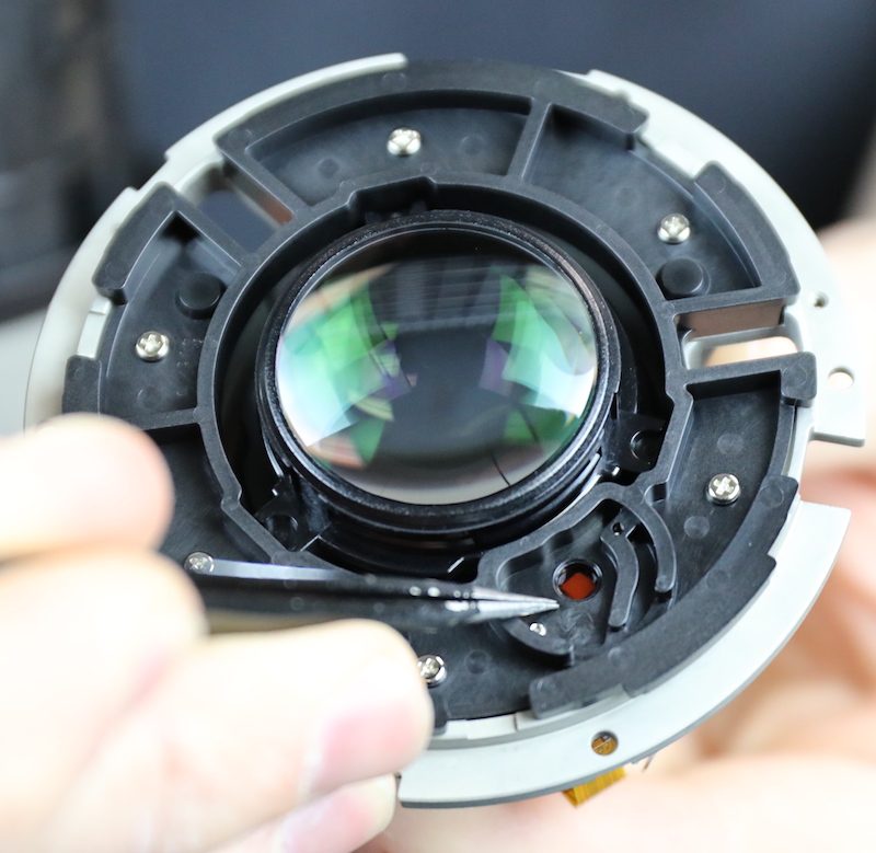
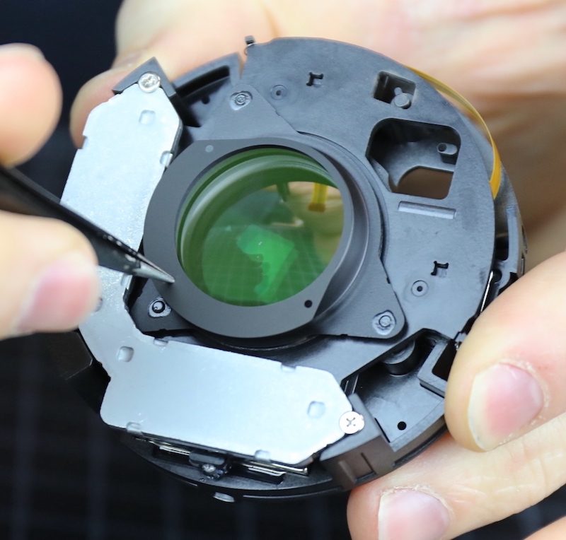
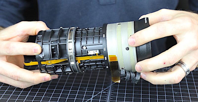
We’ll peek in the front half first, since we’re here. There’s a fixed element that comes out easily enough.
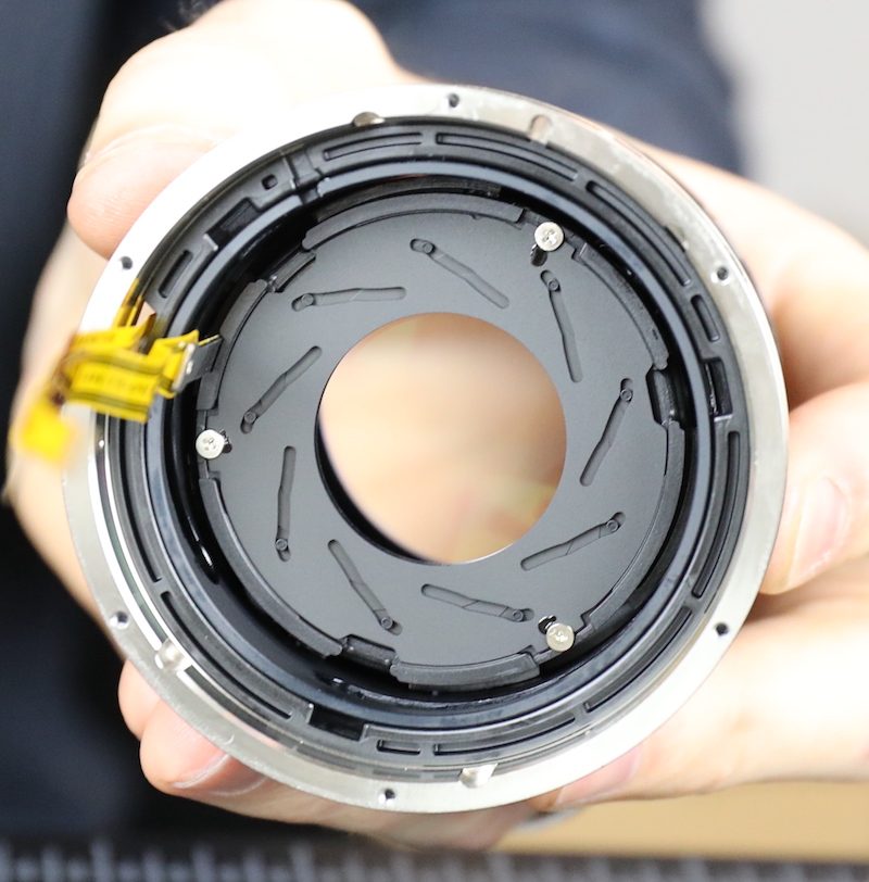
And then we have a nice look at the aperture assembly. We didn’t bother to take it out, but in retrospect, it would have given us a look at the back of the zoom elements. Sorry.
Same as It Ever Was
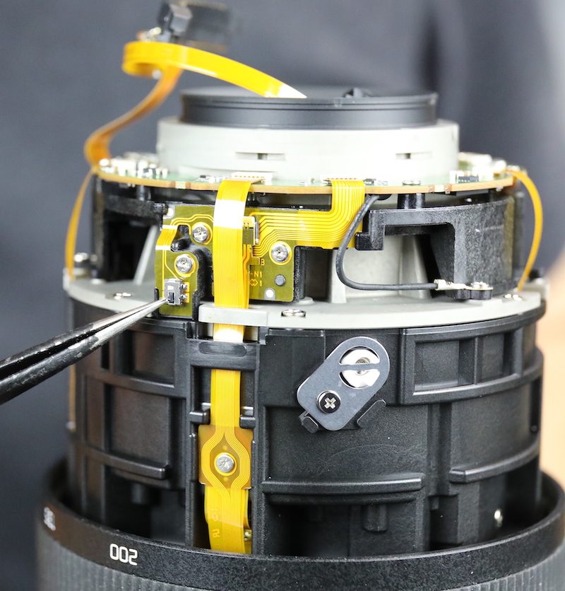
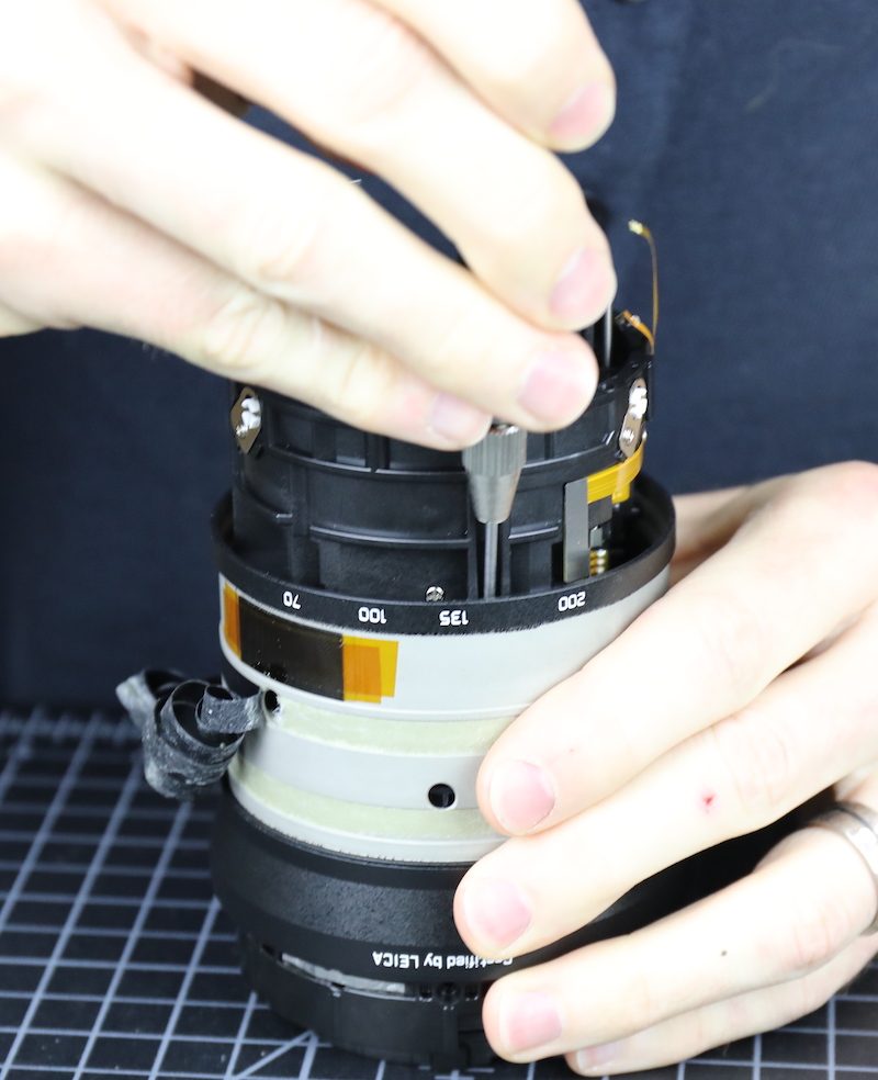
Now it was time to take a look at the linear focusing motor and see if we can find an issue. Given that we still don’t even know what the Unknown Sensor of Unusual Size was, and that there were some things in this lens that were really different than most, we weren’t optimistic.
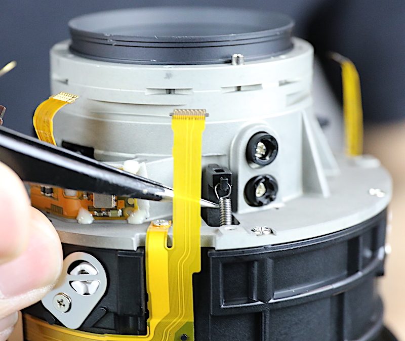
There are some flexes to disconnect and get out of the way first.
Then we take out the secondary sliding rod (the primary rod is still in place in the right foreground). along with the upper stop plate and corner bumpers
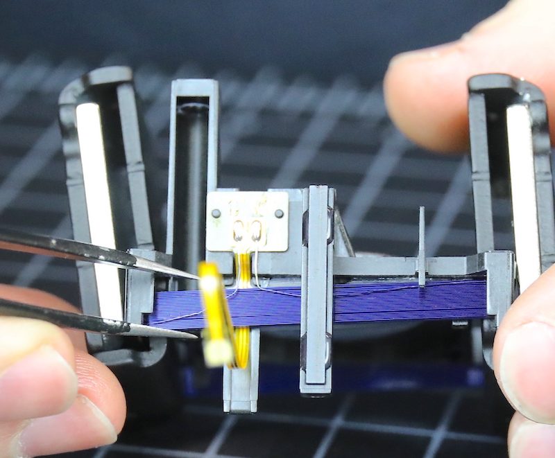
After which the focusing assembly slides right out. The focusing group is in the middle with pretty purple electromagnetic coils running around the sides. To either side are the permanent magnets; the silver plate is the actual magnet, the darker metal pieces are the housing. These magnets are quite strong; you can separate the housing pieces by pulling them apart, but the magnetic force is strong enough that it requires two hands and a strong tug.
The problem is immediately apparent. The electromagnetic coil was only glued to the focusing group plastic and the glue has come loose, only remaining attached at one side. The focusing group is tilted compared to the motor and isn’t going to move well, if at all.
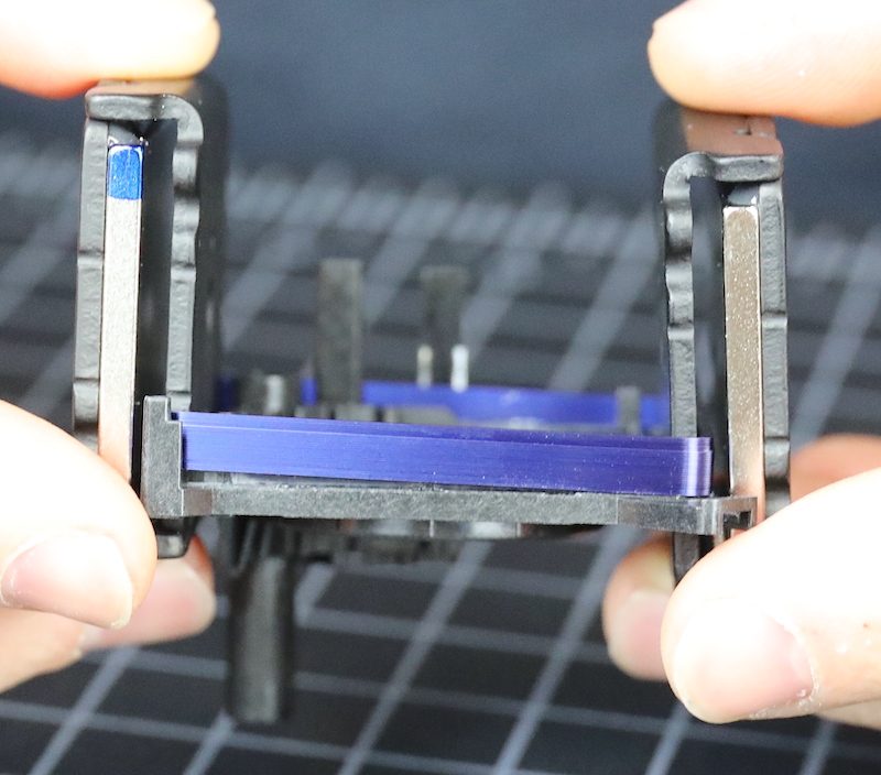
The reality is that glue can fail under the fast, repeated vibrations of a focusing motor. We found this kind of problem in the first generation Sony and Zeiss linear motor lenses back in 2015. And a couple of years later we found that newer generations of those lenses all put cages, tabs, and other things to help hold the electromagnet in place, they didn’t just rely on the glue.
I assume the motor manufacturer (who probably isn’t the name on the outside) felt this square design going around the entire circumference would hold in place with just glue since there’s a large surface area to glue in this square mount. (Those earlier lenses had had a much smaller area of glue attachment). It appears they were not as correct as they would like to have been.
So, What Did We Learn Today?
Well, obviously we learned that Panasonic doesn’t read our blog; or at least they didn’t back in 2015 and 2016 when we first described this problem. I’m not surprised at that, but still, they certainly knew all the other manufacturers changed from just glue.
For us, this is the best possible result. We did this kind of repair on linear motors for years and we can do it again. That’s much better for us than sending the lens off for weeks and paying a large fraction of the new-lens price for a replacement.
For those of you who own this lens, let me say clearly that our lenses get used heavily and only a small fraction of them have developed this problem; under 10%. So chances are you won’t see this happen to your lens. If your lens does stop autofocusing, though, I strongly recommend not trying this at home. It’s not an easy disassembly.
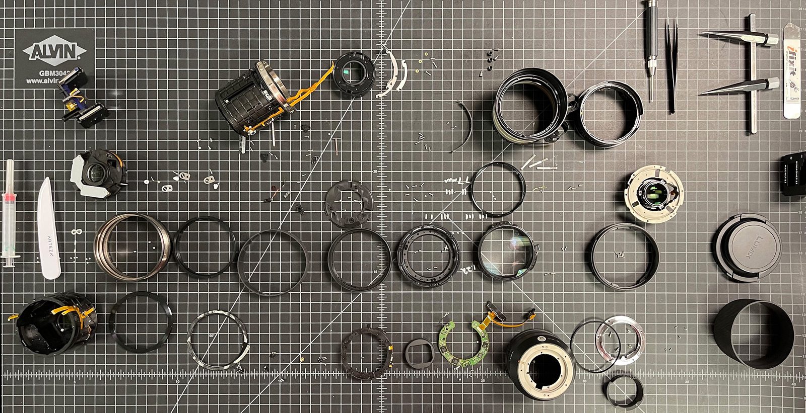
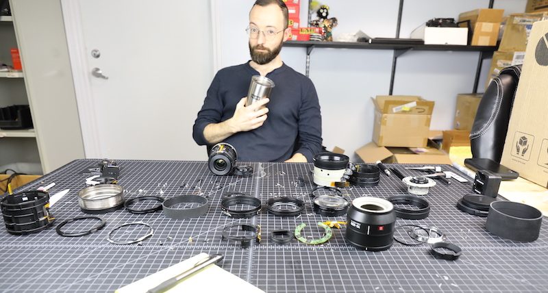
I’ll leave you now with one last picture to emphasize what you’d have to put back together should you successfully take it apart. And yes, Aaron is looking quite pleased with himself. We were both really surprised to find something we could fix.

26 Comments
Clayton Taylor ·
The Acronym Police have begun an investigation – if the name is Sensor of Unusual Type and Unknown Function, then it should be SUTUF, not SUTUS, correct? Unless your original name for it ended in “Specification”, not “Function”.
Later on, you refer to it as the Unknown Sensor of Unusual Size – that would make it an USUS. Continuity check, please……
This after you you took a shot at Panasonic’s proofreaders, too. Tsk, tsk….
The happy ending to the AF dilemma more than makes up for the bumps in the road, but I am curious as to WHAT your “fix” was – more glue for the electromagnetic coil, or did you guys enhance the repair with add-on restraints?
Roger Cicala ·
You are correct, I changed that name in every draft as we changed our mind what it was. Until we finally gave up trying to understand. Probably will just leave it as a testament to our confusion.
Yes, we reglue them; that’s what we’ve done before. We possibly could plastic solder a bit of a cage, but we’re concerned with any change to the balance or weight would affect the AF system. We reglued several dozen of the old Sony lenses and it worked well; I think we may have had one secondary repair.
Alan ·
Have you disassembled any Olympus Pro lenses with IP53 ratings? It would be great to compare how small or big the difference is with those lenses and other weather resistant lenses.
OMDS retroactively certified to IP53
8/1.8
7-14/2.8
8-25/4
12-100/4
40-150/2.8
300/4
150-400/4.5
Roger Cicala ·
Alan, we haven’t.
Alan ·
Is there anything to comment on whether this is due to the build consistency (you don’t NEED to repair stuff because of engineering choices) or the turnover (the most popular Olympus Pro lens having been rented out x% of the volume of a Canon/Nikon/Sony equivalent).
Roger Cicala ·
These are not what we would consider heavy renters compared to Canon/Sony. Regularly rent, but no pent up demand.
Henry Winokur ·
I’m curious what kind of glue you used?
Andreas Werle ·
Finally another Disassembling!
And no disappointment at all: glued electromagnets and a flex cable soldered to wire, when did we see this the last time? (Nikon if my memory is correct.) Honestly i hope you have not so much broken Lumix-Lenses, what a bloody awful mess – poor Aaron! Thank you so much anyway, much appreciated!
Greetings – Andreas
Roger Cicala ·
Greetings Andreas! You do have an excellent memory.
Andreas Werle ·
Roger, i have googled a bit to find out, what the numbers on the Sutus could mean. SPU can be a "Synergistic processor unit". UL 94 (refering to 94V-0) designates the " Standard for Safety of Flammability of Plastic Materials". Guess this is not of help to identify the device, just fun. :-)
Andreas Werle ·
Roger, i have googled a bit to find out, what the numbers on the Sutus could mean. SPU can be a “Synergistic processor unit”. UL 94 designates the ” Standard for Safety of Flammability of Plastic Materials”.
Roger Cicala ·
Thank you Andreas.
John Frantzen ·
Interesting. Makes sense. Excellent descriptions and photos. Fun. Thanks!
Jim A. ·
SPU-F1…Supercharger Power Unit, Formula 1! Clearly the purpose of this component is to enhance the zoom power, I’m embarrassed that the marketing group missing the clear opportunity to brag about this critical, breakthrough feature. But seriously, once again, you impress us with the great details and entertaining writing describing a quite challenging disassembly.
grubernd ·
Sadly there is no clear image of what the USU (unknown sensor unit) is looking at .. that might give us a clue what it’s reason is. Unless of course it is an engineers joke directed at folks like Roger and Aaron and USU is just a Useless Sensor Unit.
Roger Cicala ·
Aaron and I have discussed this on several disassemblies. “They just put it in there cause they know we’re gonna look.”
Not THAT Ross Cameron ·
Woohoo,
Disassemble, disassemble, disassemble!
Out of curiosity, do you know if such decisions have consequences for the manufacturer, over time? Extra cost in repairs etc?
At least there wasn’t any sticky tape holding it together.
Roger Cicala ·
They do, at least in repairs and customer dissatisfaction. And I’m sure internally there are some tough talk amongst engineering groups. We see problems in a design every so often, they are almost always denied publicly, and then are fixed in the next generation.
Henry Winokur ·
Great and fascinating write up, Roger. Aaron must have very steady hands. You guys are having way too much fun. What’s next?
miao ·
Hi Roger, haven’t seen you update any new MTF test blog for a long time, any plans to test new sony GM lenses and canon RF lenses? Really looking forward to those, thanks!
Roger Cicala ·
We’re on hold there. As you probably know we had a long delay in getting RF and Z mounts for our bench, then things just got backed up with various shortages. Doing 10-lens MTF testing requires more time and resources than we can dedicate right now.
PeteyKay ·
I thoroughly enjoyed the blog post about the Lumix 70-200. A great read with great photos. Very impressive disassembly. Thank you.
Jeremy Dorrough ·
Can the front element be removed without the rest being disassembled? I have fungus under the front element:
https://uploads.disquscdn.com/images/ff2908ff7cac9b40fdfc23cc80c6ec369eab9503fe44c81b38789ce0752087a8.jpg
Stephanie ·
Hehe… What?!
Grummbeer Bauer ·
I keep returning to the lens rentals Blog, mostly for Roger’s geeky, always highly informative and fun-to-read articles. Alas, there haven’t been any for a long while. ?
I wonder if this is just a hiatus, or permanent retirement, and that he is well.
Spookeo ·
Nice teardown. Do you happen to know how the focus clutch is triggered? My Lumix S Pro 50mm F1.4 since updating the firmware has inverted! I'm wondering if it's a simple thing I can swap on the hardware? Thanks