Equipment
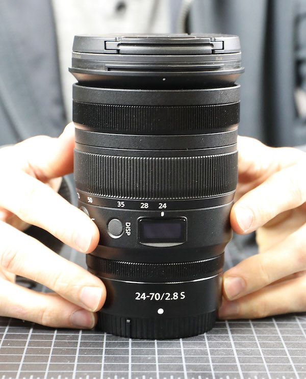
Finally, the Nikon Z 24-70mm f/2.8 S Lens Teardown

Just so you know, my original title was “Lens Disassembly is a Complicated Profession. Don’t You Agree?” The editor said nobody would know what the post was about. But I promise, you’ll see by the end of this; lens disassembly is a complicated profession.
We were interested in this disassembly, and by interested, I mean both excited and nervous. We assumed that things would be very different inside from previous Nikon lenses. But Nikon lenses have always been a bit ‘old fashioned’ and different from other SLR lenses, so we weren’t sure what to expect.
Lensrentals.com, 2020
Do not get your lens and screwdriver and follow along at home. Bad things might happen. Bad. Things.
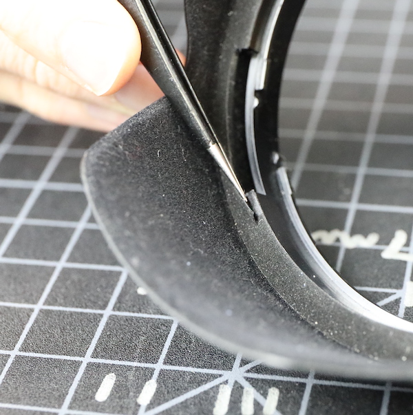
Before we start, a quick break to do some QA bitching. Nikon, do something about the felt you line the lens hoods with. It’s a really minor thing, and yeah, we can super glue it back down, but this is too frequent.
Lensrentals.com, 2020
Spoiler alert: we don’t find much else to complain about in this lens.
So Let’s Get Inside the Nikon Z 24-70mm f/2.8
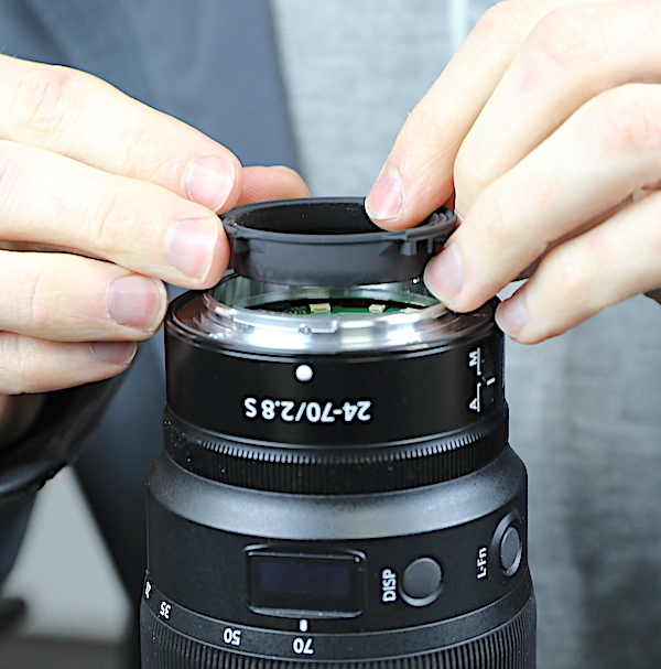
Going in from the back, we start by removing the usual three tiny screws that hold the rear baffle in place.
Lensrentals.com, 2020
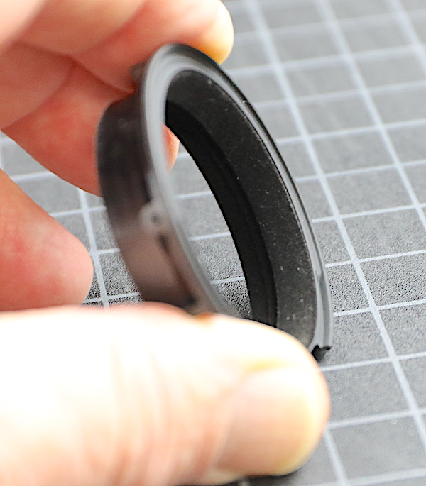
The baffle is felt-lined, whether for absorbing light or dust, or both, we don’t know. But it’s a nice touch.
Lensrentals.com, 2020
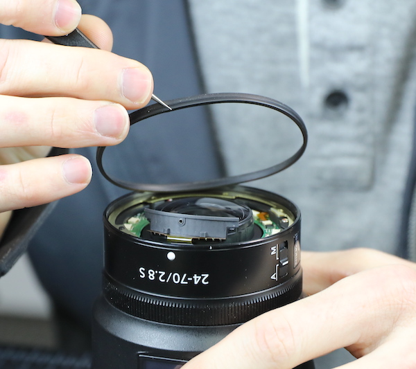
The bayonet is held in place by the usual four screws. Even after removing the screws, it took a little force to pull it off, almost a suction-like effect.

Lensrentals.com, 2020
We immediately saw the reason for this; the rear baffle has an inner lip that sits tight against the rear barrel. This might be to keep the bayonet centered, for a dust seal, to provide a little extra strength, or just because it looks cool. But after seeing it (I don’t remember anyone else that has it), it just seems like an all-around good idea. I certainly can’t think of any downside to it.

Lensrentals.com, 2020
There’s the usual rubber weather sealing ring under the bayonet.
Lensrentals.com, 2020
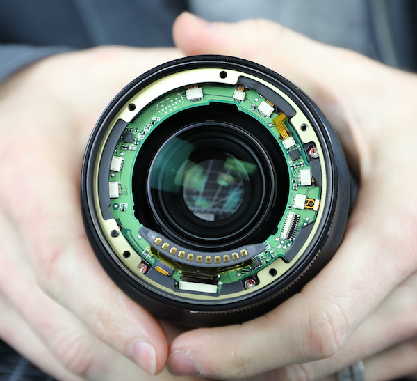
With the bayonet off, we see the PCB, and it’s flex connections.
Lensrentals.com, 2020
You may have noticed the spacing shims in the above photograph; there are three different sizes in this copy, so definitely, these are an adjustment, probably for infinity focus.
Lensrentals.com, 2020
Removing four more screws and one flex lets us remove the rear outer barrel.
Lensrentals.com, 2020
The flex goes to the A/M switch. The lens control ring is simply an optical sensor ring.
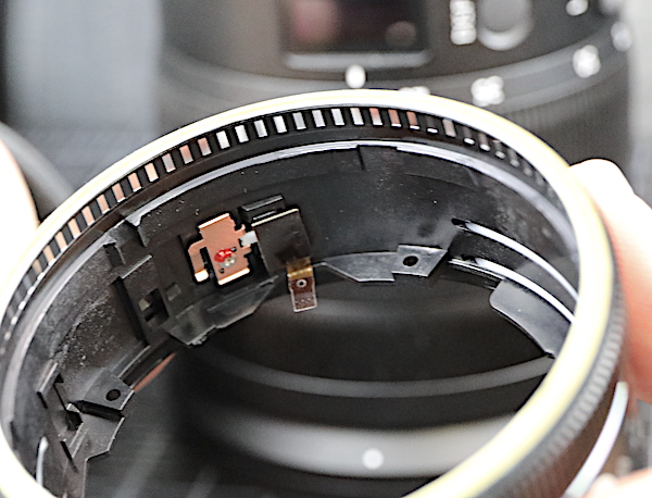
Lensrentals.com, 2020
Of course, there is a good, foamed weather seal at each barrel joint.
Lensrentals.com, 2020
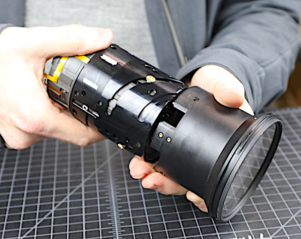
The lens control barrel isn’t attached mechanically, so these two barrels can be separated.
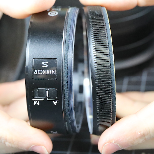
Lensrentals.com, 2020
You could see the weather sealing in the above image, but this one also shows the ESD (electrostatic discharge) cushions that are under this ring.
Lensrentals.com, 2020
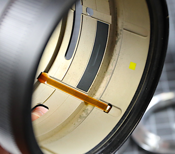
We can also see the optical sensor that is activated when you turn the control ring.
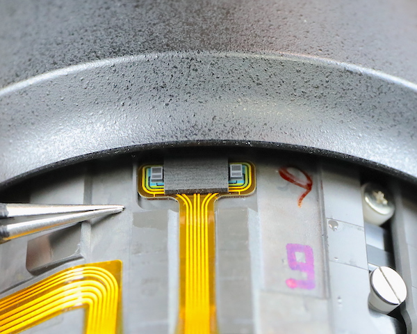
Lensrentals.com, 2020
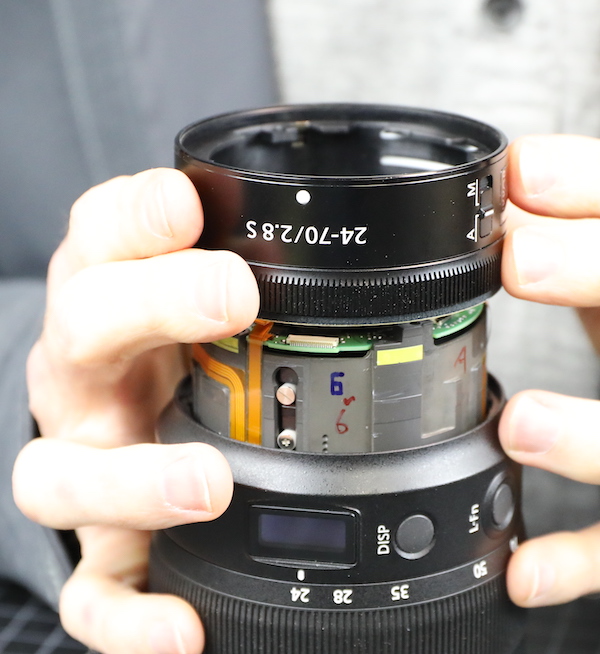
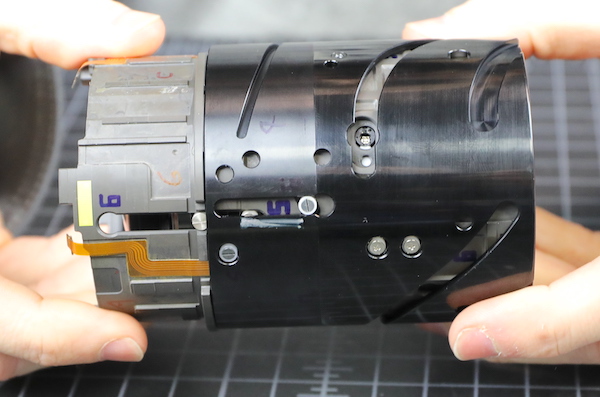
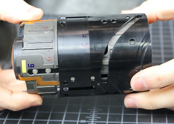
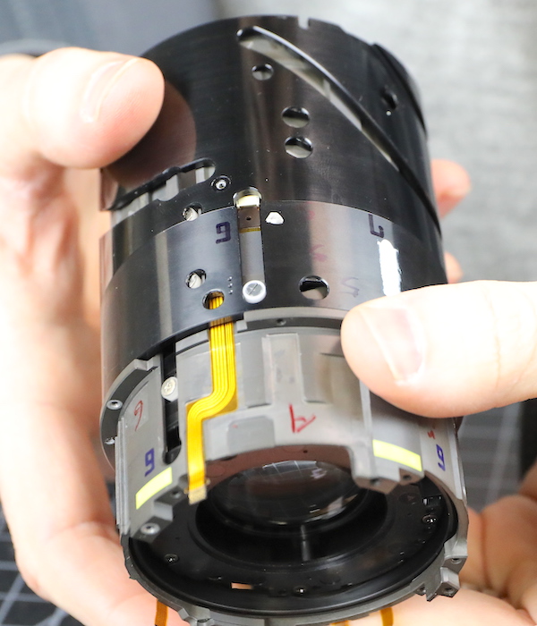
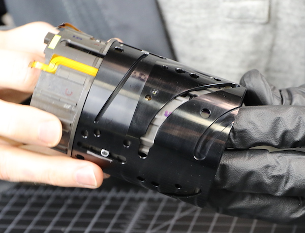
OK, let’s take a moment for me to give some props. Forever, during Nikon tear-downs, I’ve made snarky comments about the old-fashioned look they have inside; soldered wires here and there, flexes wandering aimlessly, random secondary circuit boards, etc. Well, no more. Look at this engineering right here: neat flexes running directly where they’re heading placed in recessed channels in the barrel and thoroughly taped in place. Superb!
Lensrentals.com, 2020
Nikon has clearly modernized and spent time and effort in making a clean, well-engineered layout for the electronics. I’ve been asking for that for years, and Nikon delivered. It would be a shame if, having gotten what I wanted, it ended up biting me in the ax, wouldn’t it? (I read this article about being a better writer, and it said to use foreshadowing. There you go, I foreshadowed the hell out of that, didn’t I?)
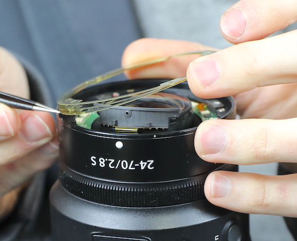
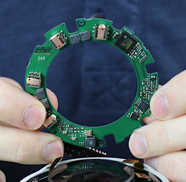
But I digress. The next step is undoing all the flexes and removing the PCB. If you compare this to the PCB in the Canon RF 70-200 f/2.8 you’ll probably notice there’s just less stuff on the Nikon PCB. We’re used to Nikon lenses having secondary circuit boards deeper in the lens and thought that was why. I’ll jump ahead and tell you there wasn’t another board, though, so Nikon probably does more electronic processing in the camera. (This was going to be more foreshadowing, except I ended up not talking about it anymore.)
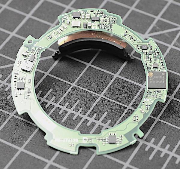
Lensrentals.com, 2020
With the PCB off, we can see there are shims under the rear group (they’re the thin brass line). These are circular, so they’re for proper spacing, not tilt.
Lensrentals.com, 2020
There’s another light baffle back here, which is always a good thing.

Lensrentals.com, 2020
We moved on to taking off the mid barrel, removing the screws that obviously held it in place.
Lensrentals.com, 2020
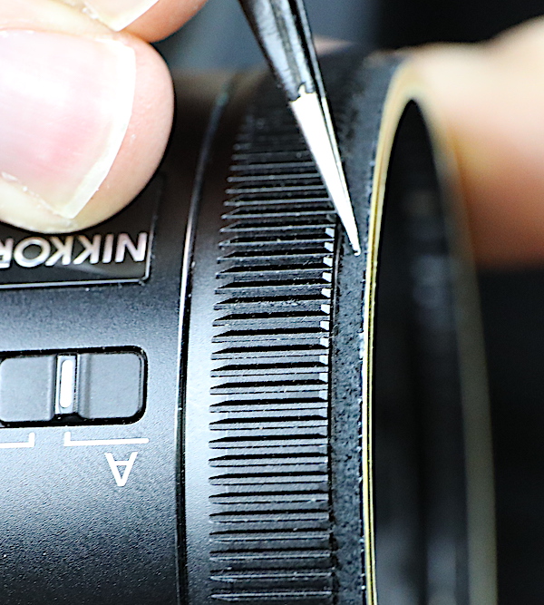
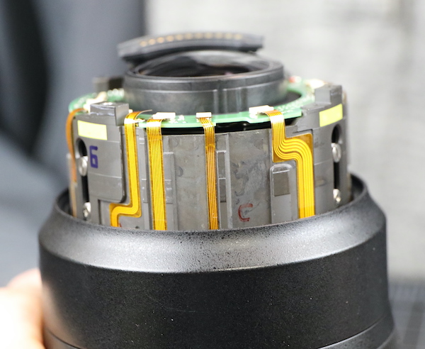
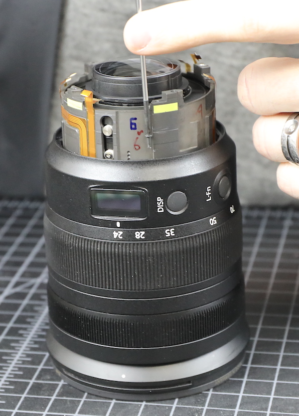
And here, as happens so many times, we ran into the ‘be careful what you wish for; you might get it’ conundrum. As I’ve wished for dozens of times, Nikon has now made a neatly engineered lens with flexes laid out logically. They went even further, building in nice channels for the flexes and thoroughly taping each flex in its proper place.
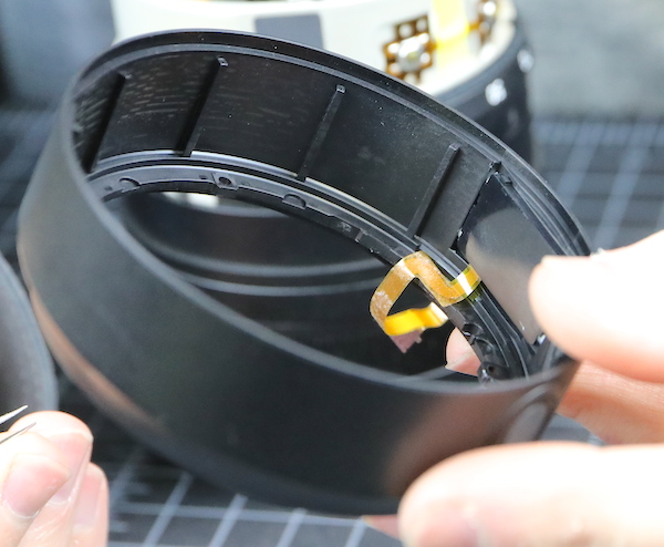
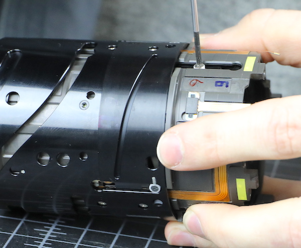
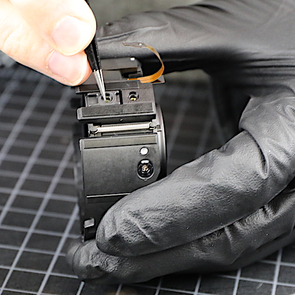
One of those flexes (the one sticking up on the left) runs down to the display unit in this barrel. We untaped it where we could reach it, but it was still taped down somewhere underneath that ring. Aaron could feel the tug when he started to pull up the barrel.

Lensrentals.com, 2020
Rule 63 of taking apart lenses is ‘thou shalt not tug a flex’; because tearing a flex is bad. On Nikon lenses, because we can’t buy parts, tearing a flex is very bad.
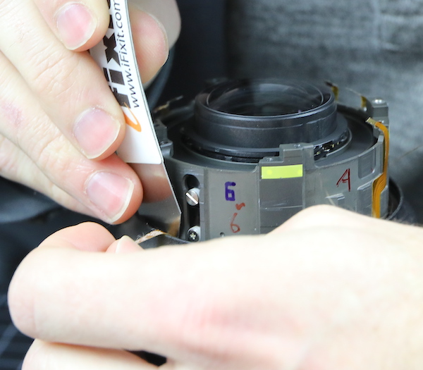
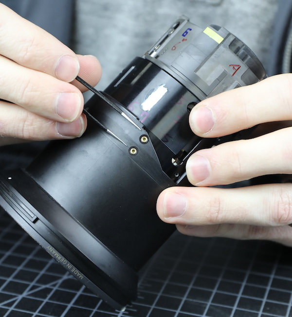
We used every type of flat instrument we had to free the flex up, from spunger to bamboo sliver, but the tug remained the same.
Lensrentals.com, 2020
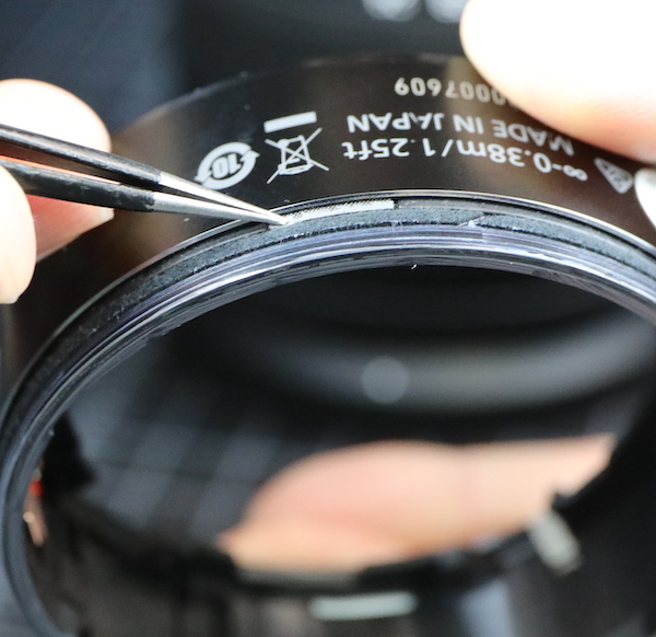
We even removed the rubber and the underlying shield tape to see if we could get a look from the other side.
Lensrentals.com, 2020

Lensrentals.com, 2020
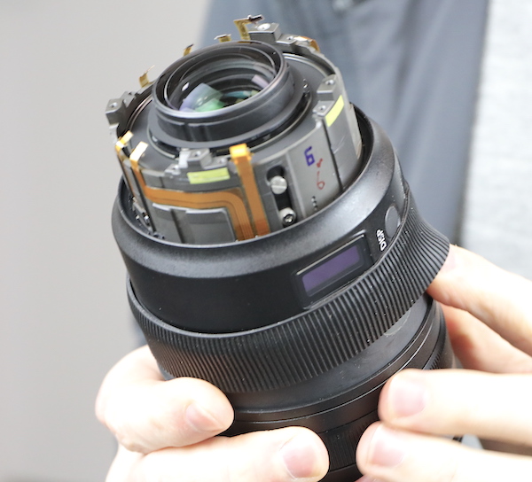
Tape is probably an inadequate description; that’s a nice piece of 0.5mm heavy-duty plastic. Despite all this, the bottom line is 45 minutes later, we still hadn’t gotten the display barrel off and couldn’t see where the flex was stuck. This is why we don’t do videos of teardowns; they’d be incredibly dull.
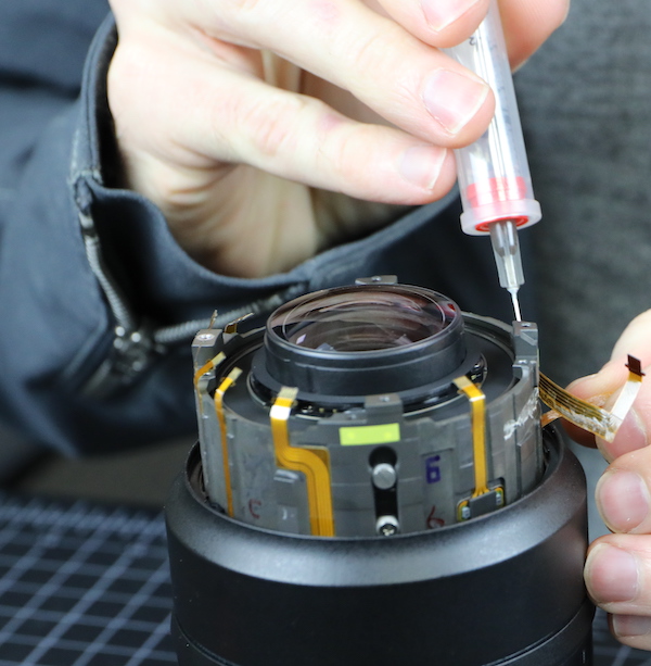
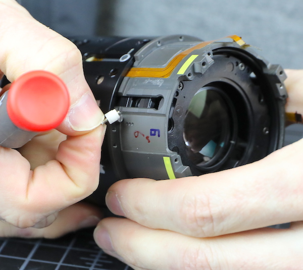
Many of you know my attention span is limited, so I suggested we inject alcohol into that area to loosen the adhesive and then pull the ring off, or let her rip, whichever happened. It’s been years since we damaged a lens during a disassembly. We were concerned that streak was about to end, but it was getting close to lunchtime, and we were hungry.
Lensrentals.com, 2020
The ring came off with no damage to the flex, and now we could see why it stuck; we could free up the part that went straight down, but after we lost sight of it, the flex had two right-angle turns, both of which were taped down. However, those two bends took all the direct tension off of the flex during removal, so there was actually little danger of tearing it.
Lensrentals.com, 2020
While we were looking around, though, we did see that there was a nice adjustable eccentric collar under the display ring. It has a very nice touch; the zero position is marked on it. You don’t care, I know, but for people working on the lens ‘zero mark at 12 degrees forward’ is a lot more accurate than ‘the fatty part is towards the front a bit’. It makes us sound all professional and such. After that flex fiasco, we need to sound more professional than ‘put some alcohol up in there and give it a tug’.
Lensrentals.com, 2020
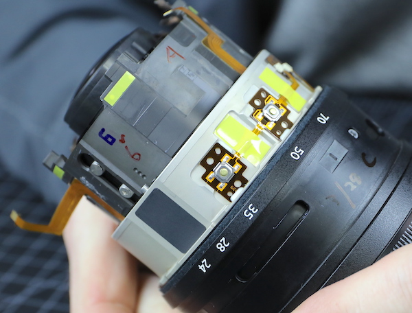
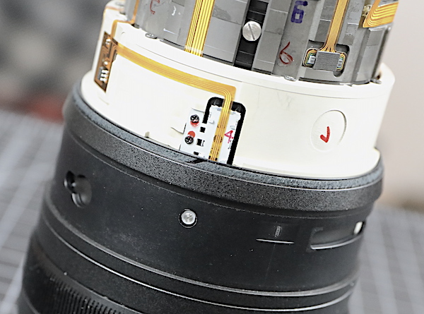
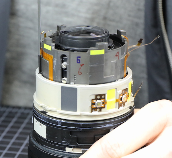
A look underneath the display ring shows you the button on the ring, just a rubber stopper that pushes the real button underneath, which allows more complete weather sealing. To the left of the buttons, the gray plate is an anti-reflective/antiglare plate that was under the actual display. Finally, you’ll notice there’s a lot of yellow tape. This decorating theme is carried throughout the disassembly and gives the lens a bright, beachy feel (yeah, I been watching HGTV some). As we’ll discuss in a bit, this tape has a really practical purpose.
Lensrentals.com, 2020
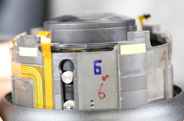
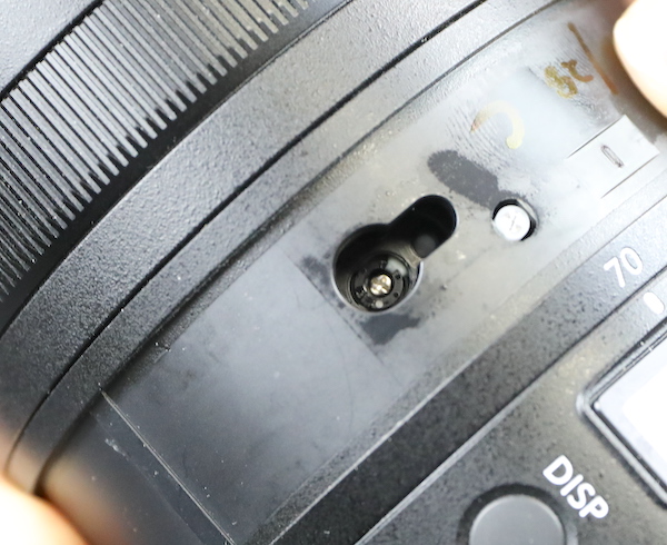
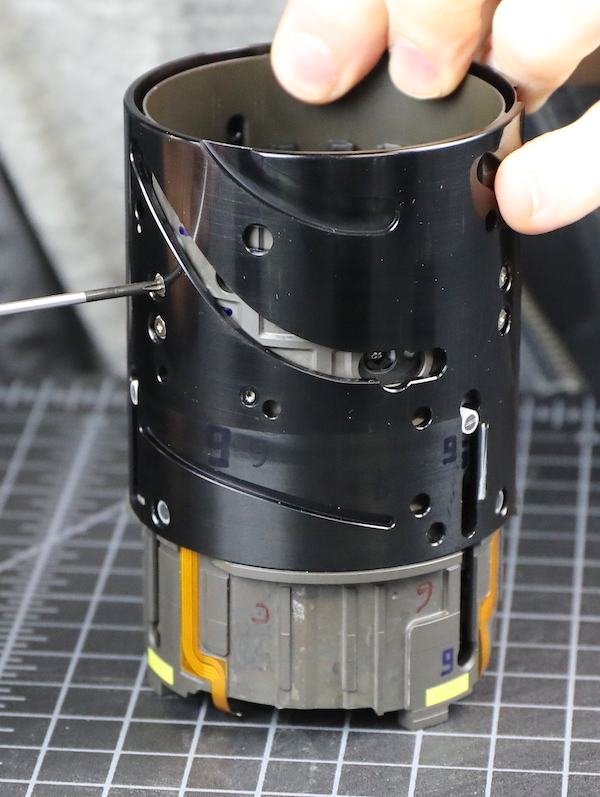
The zoom barrel is next up. There are mechanical zoom stops (the two slotted screws) that are nice and robust, and again, good weather sealing between each outer barrel.
Lensrentals.com, 2020
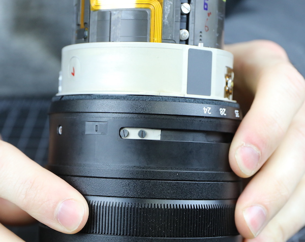
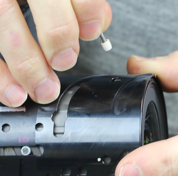
Turning the lens a bit, you can see the zoom position sensor (Nikon has finally moved on from metal brushes) and one of the zoom ring keys (small slotted screw with white nylon collar) that attach the zoom ring to the cam barrel.
Lensrentals.com, 2020
All of those things are removed next to take the zoom barrel off. The zoom keys are heavy-duty, as you’d expect. Aaron here exhibits the ‘balance screw-on blade of screwdriver maneuver.’ This is the Geek equivalent of spinning a basketball on your fingertip. We’re like the Harlem Globetrotters of lens disassembly.

Lensrentals.com, 2020
With the hardware out, the zoom ring slides right off. We’ll look fondly back on this step, because ‘slides right off’ isn’t going to happen much more.
Lensrentals.com, 2020
Underneath the ring is the ESD pads that we got a peak of earlier.

Lensrentals.com, 2020
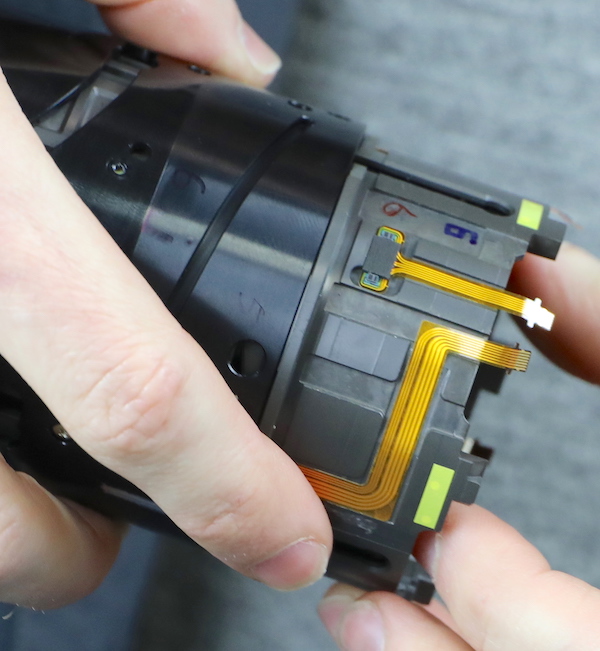
The next step is to unhook the flexes and sensors at this level. As you can see from the image above, Nikon puts actual connectors in the flex runs that can be disconnected; we much prefer that rather than long runs of a single flex that has to be traced and untaped.
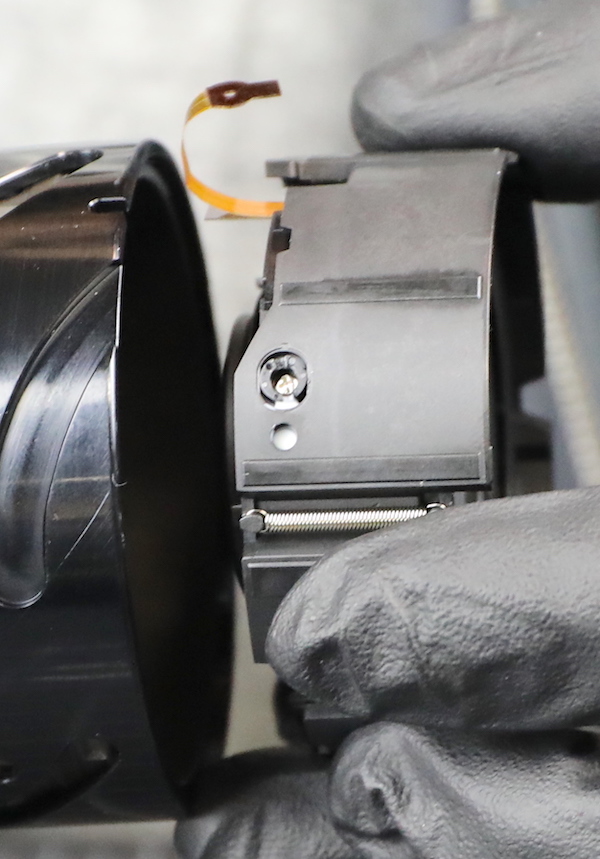
The electronic zoom sensor is held in place by a couple of screws (already removed in this image).

Lensrentals.com, 2020
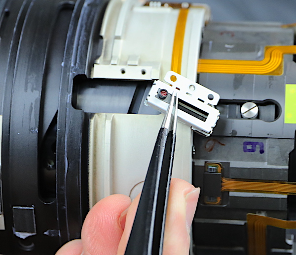
This is a self-contained unit. On the backside is a small cam that inserts into a barrel slot. Rotating the zoom barrel moves the cam up and down, and the sensor reads that position.
Lensrentals.com, 2020
With all of that stuff disconnected, the next step is obviously to remove the inner (white) electronics barrel.
Lensrentals.com, 2020
Except, well, it wouldn’t slide off despite Aaron spending 30 minutes doing various zoom and focusing ring position changes. It was like watching a safecracker trying to find the right combination and failing. We just couldn’t remove the rear inner barrel.
As I mentioned earlier, I am not a patient man. My suggestion of ‘get a saw’ was overruled, and instead, we took a lunch break to regroup. To put it in perspective, lunch is usually between disassembly and reassembly. Here it was lunch break, and we weren’t even halfway done with disassembly.
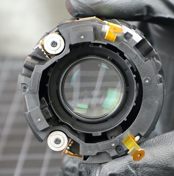
After lunch, we did a reverse and decided to take out the front extending barrel. Like the Canon RF lens, the Nikon uses pairs of rollers, two in each slot. This should prevent any barrel sag in the extended position. The hardware isn’t as robust as Canon’s, but certainly seems adequate for the job.

Lensrentals.com, 2020
With those removed and a few more things detached, we were able to slide rear inner barrels off as a unit.

Lensrentals.com, 2020
So basically, you have to remove most of the front barrel hardware to take off the focus ring and rear barrel. We discussed the various reasons this would be so and concluded, “make Roger and Aaron look foolish during a tear down” was the most logical.
I’ll take a moment to discuss that pretty yellow tape we’ve seen scattered about the lens. It was about now we realized that the tape was placed inside of every screw hole in the lens, and its reason became apparent. It’s for what we refer to as FELD (First Expensive Lens is Dusty) syndrome. That’s where buyers of expensive lenses look inside, see dust, and lose their mind because they think lenses are assembled in NASA clean rooms, and ‘weather-resistant’ means ‘hermetically sealed like a vacuum jar.’
Lensrentals.com, 2020
But even I admit they have a point when a brand-new lens gets a huge spec inside. The answer to ‘how did a huge spec get in there’ is generally Loctite. All the screws have Loctite to hold them in place, but extra dried Loctite can break off and become that ‘huge’ chunk of dust in the lens. (Huge usually equals about 0.1mm to 0.2mm; but lenses, as we learned in grade school, make things look bigger.) That yellow tape everywhere prevents any Loctite around the screws from getting down into the optical parts of the lens. Nicely done, Nikon. Very nicely done.
Another nice touch is Nikon has put line-up markings throughout the lens so that during reassembly, you know precisely how round pieces are supposed to line up. (If you haven’t done a reassembly, I should mention that most pieces will fit in any of 3 different rotations. That’s why you see us putting little marks on them during disassembly.)
Lensrentals.com, 2020
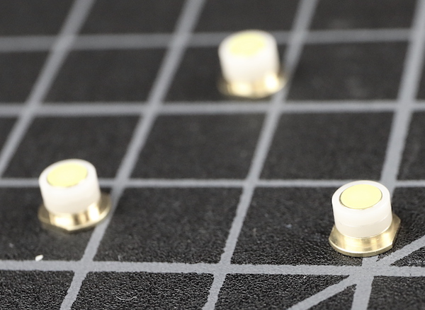
With the barrel off, we can now see those screws and collars we removed insert into nice brass inserts, no screwing into the plastic.
Lensrentals.com, 2020
There is also a second set of screws holding the front barrel on to the inner assemblies. The triangle just above the screw is another lineup marker.
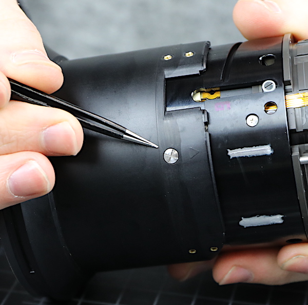
Lensrentals.com, 2020
Removing these screws let us slide the extending barrel off.
Lensrentals.com, 2020
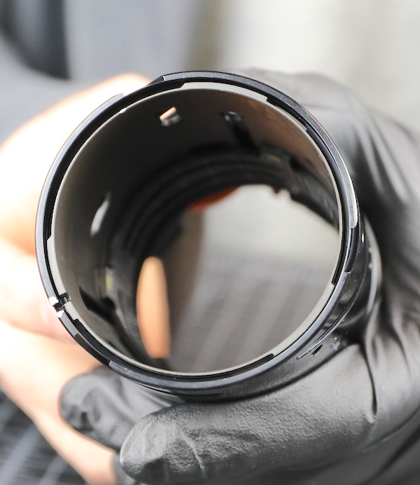
Inside, you can again see that yellow tape covering the internal opening of all the screw holes.
Lensrentals.com, 2020
Even the insides of the pressed in brass screw slots are taped.
Lensrentals.com, 2020
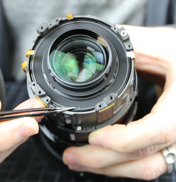
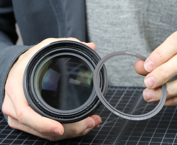
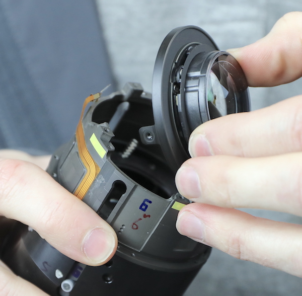
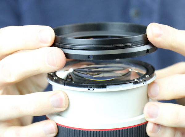
There is already some bad news about the front barrel, but to decide how bad we need to take the front element out. As seems to be the norm for this lens, we spent some time in quiet contemplation. (Quiet Contemplation, of course, means softly muttering unlikely descriptions of the possible parentage of this lens.) We saw no screws; we saw no makeup ring that might cover screws, we just saw nothing.
Lensrentals.com, 2020
Finally, Aaron found an almost invisible seam that indicated a possible makeup ring and using the rarely required thumbnail tool was able to remove it. That revealed the spanner slots in the front element, so it just unscrews from its seating. Props again, though, because being unable to see the seems is an indication of how precisely even these decorative parts are being made.
Lensrentals.com, 2020
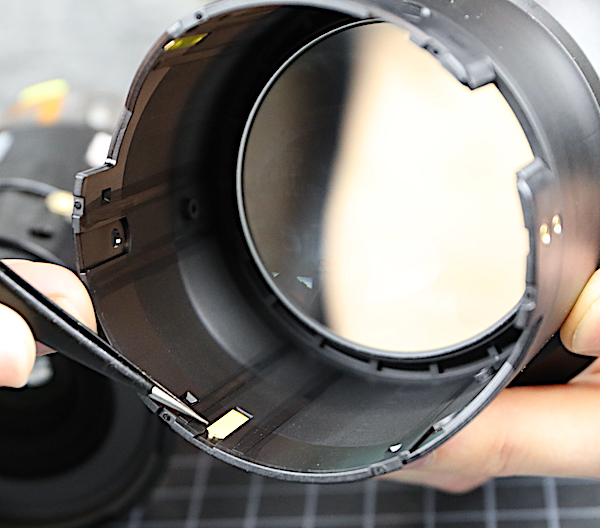
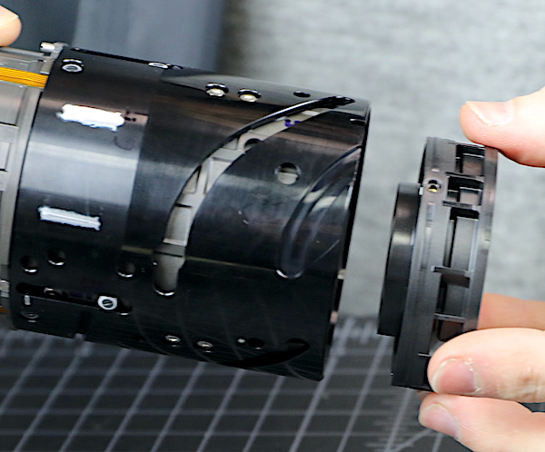
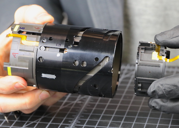
Now, here’s the bad news. If you notice what Aaron is holding in his right hand below, it’s one piece. So if you break off the filter ring or hood slots, this is the disassembly that has to be done to replace it. When a lens is designed to be repairable, the filter/hood ring is a separate part, and you take out three screws and replace it in 10 minutes. For this lens, replacing a broken filter ring means a major disassembly to replace the front barrel. It will not be cheap. It will not be at all cheap.

Lensrentals.com, 2020
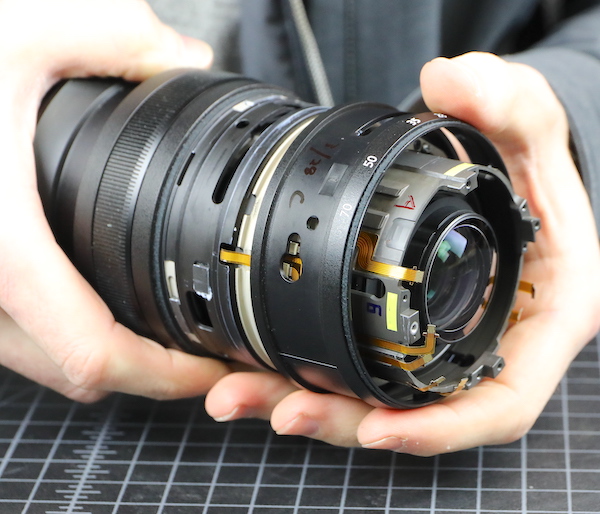
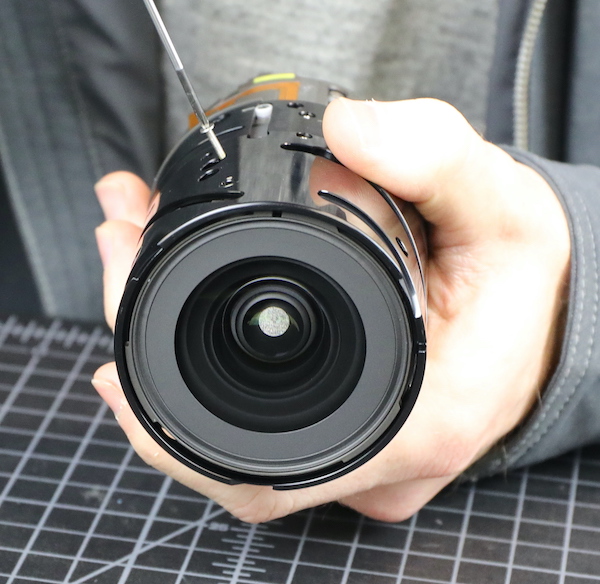
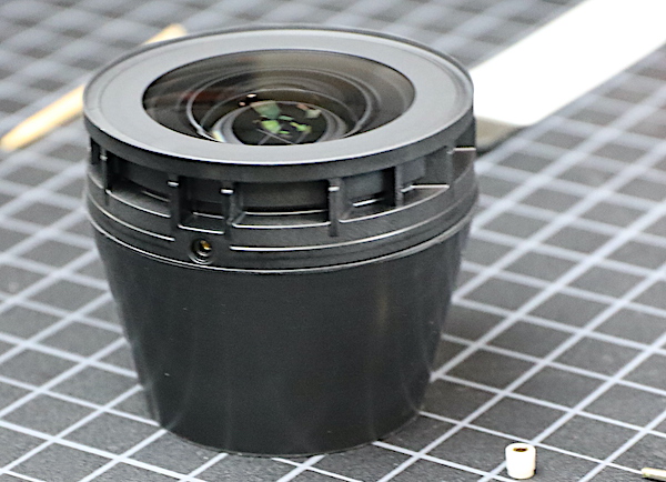
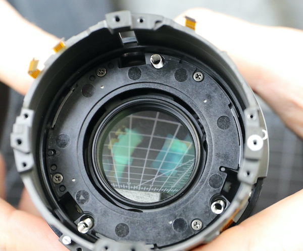
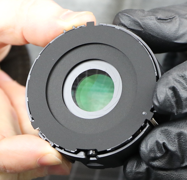
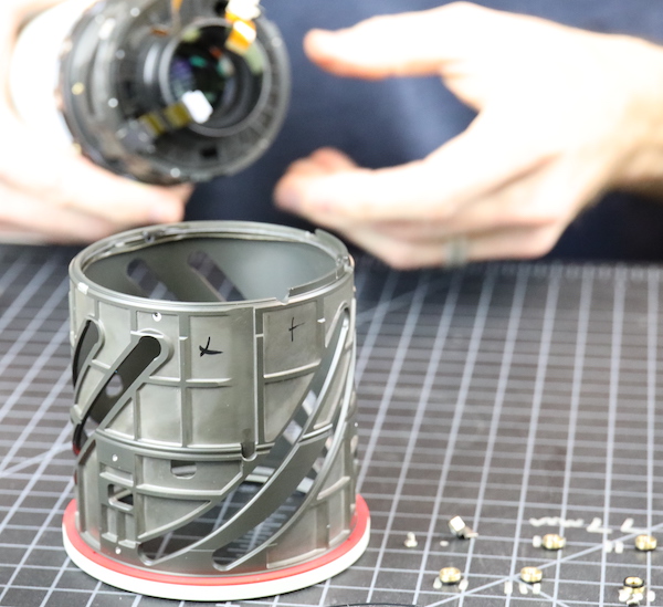
The inner optical barrel is pretty nicely exposed now. This contains all of the optical elements other than the front, the focusing motors, aperture assembly, and of course, the cams and barrels for the zoom elements. You can see one of the eccentric collars showing through one of the zoom slots and a fair number of screws and collars for the inner elements.
Lensrentals.com, 2020
Rotating the barrel shows the focusing range. Note the rear element poking out in the image below, and the distance the rear element cam screw has traveled compared to the image above.
Lensrentals.com, 2020
The logical next step is to remove the second group, which is not an adjustable element. Each of three long screws is removed.
Lensrentals.com, 2020
Then a puller is used to remove each collar.
Lensrentals.com, 2020
After which, the second group slides out of the barrel.
Lensrentals.com, 2020
And then gets set in a safe place. Some new coatings are used on these elements, so we’re avoiding touching; some coatings are more delicate than others.
Lensrentals.com, 2020
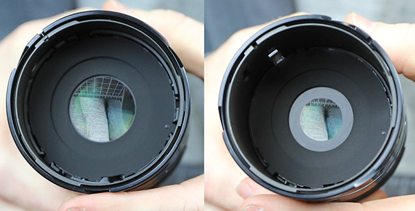
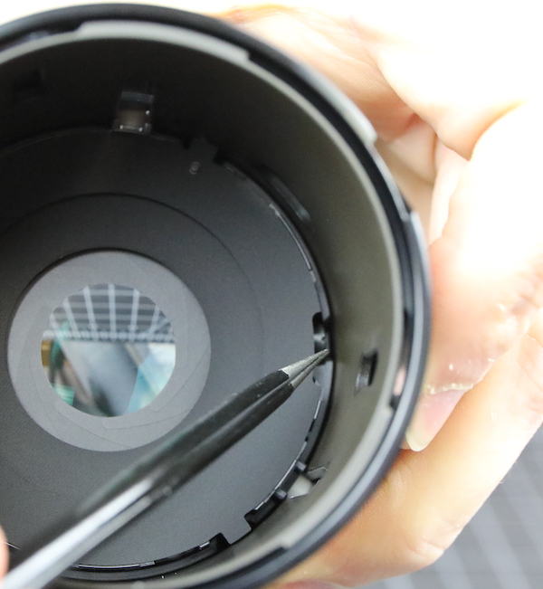
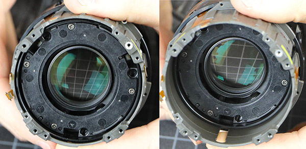
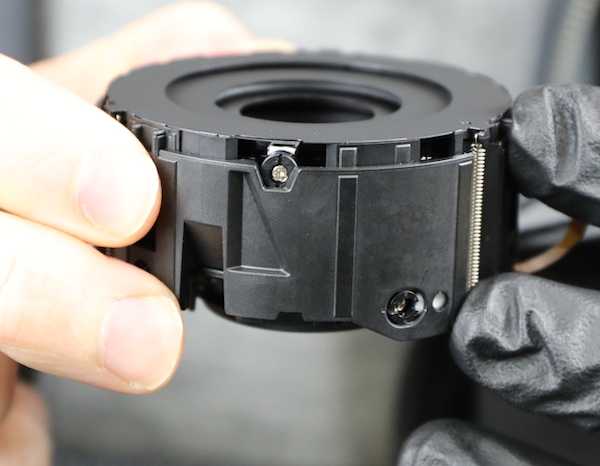
Going back to the optical barrel, we get to see something we don’t see this well very often – the working of a secondary aperture. A fixed aperture zoom has to change the absolute aperture size as the focal length changes. At 70mm f/2.8 requires a 25mm aperture, at 24mm f/2.8 requires an 8.6mm aperture.
The Nikon does this mechanically. As you can see in the images below, as you move the zoom back from 70mm, the secondary aperture closes. (Note: like the rest of this disassembly, we were wrong about this being a secondary aperture, as you’ll see later.)
Lensrentals.com, 2020
The mechanism is simple and elegant (although a bit hard to see). There’s a cam that inserts into the zoom barrel, changing the size of this secondary aperture as you zoom. You can’t see it from the image, but the post is eccentric, it would be adjusted during assembly to fine-tune the aperture size accurately.
Lensrentals.com, 2020
The next obvious move was to take off the rear element. The posts removed quickly.
Lensrentals.com, 2020
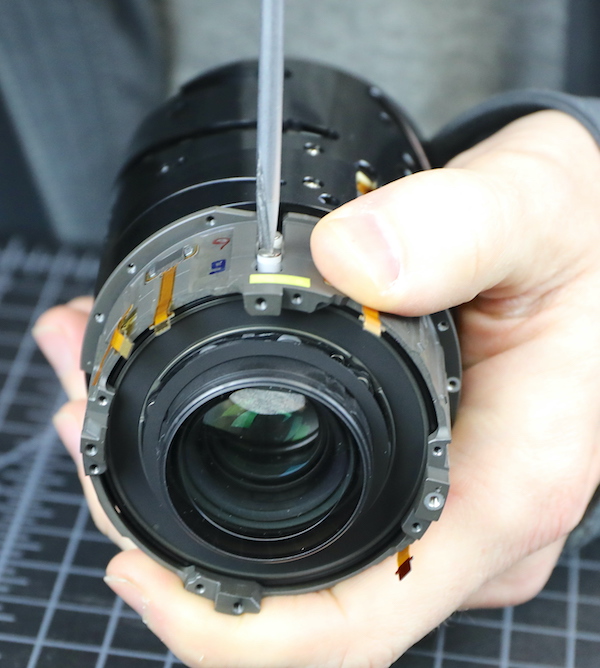
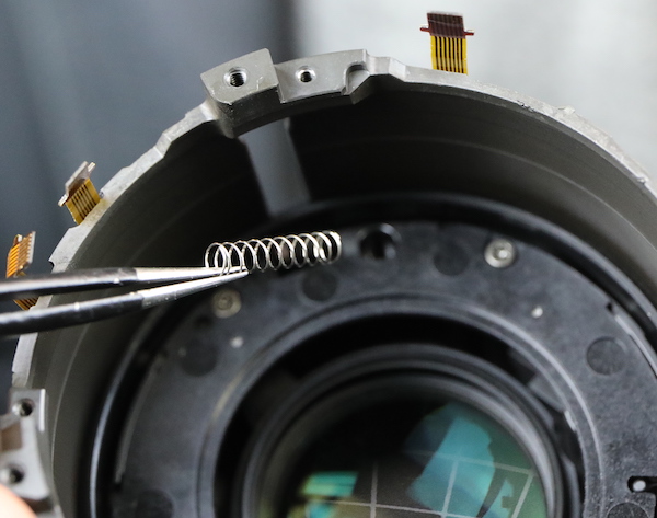
After the second one was removed, it became apparent there was some mysterious force pushing the element up. This isn’t Aaron’s first rodeo, and he kept a good grip on the rear element as he removed the final post. You can see the force, at least one of them, inside the barrel in the image below.
Lensrentals.com, 2020
There is a set of three springs keeping separation force between the rear element and the main focusing element.
Lensrentals.com, 2020
The springs sit about 1/3 of their length in fairly deep wells in the back of the focusing element.
Lensrentals.com, 2020
And shallower wells in the rear group. Why springs, you ask? I don’t know. It is the way. Notice again the yellow tape placed beneath every screw hole. Very thorough.
Lensrentals.com, 2020
Here’s a look from inside at the travel of the focusing group.
Lensrentals.com, 2020
Now we’ll move on to the next episode of “Roger and Aaron make bad choices.” We still have a couple of helicoid barrels, focusing and zoom lens groups, at least one adjustable group, the aperture, and the focusing motors in a fairly compact piece that needs to be disassembled.
Lensrentals.com, 2020
The focusing group is right there at the back of the lens, held in place with collars and screws, so that was the obvious choice.
Lensrentals.com, 2020
Lensrentals.com, 2020
Except we discovered that once it was fully released and free in the back of the barrel, the focusing group won’t fit through the rear of the lens barrel.
Lensrentals.com, 2020
Now there will be a 20-minute break while Aaron replaced collars while holding the group, so it didn’t fall forward and bang into stuff. Once that’s done, we went back around to the front. Avoiding the adjustable collar was high on our list of goals, and there seemed to be a set of 6 screws and collars that would let us take something out of the front. (We couldn’t see exactly what was going to come out at this point, but we were comfortable something would. I mean, it got in there somehow, and somehow wasn’t through the back.)
Lensrentals.com, 2020
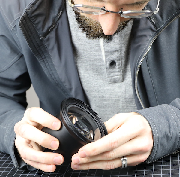
You know shit’s getting real when Aaron puts on gloves. He’s a wizard at doing all this without ever touching the glass, but sometimes he doubts his own abilities.
Lensrentals.com, 2020
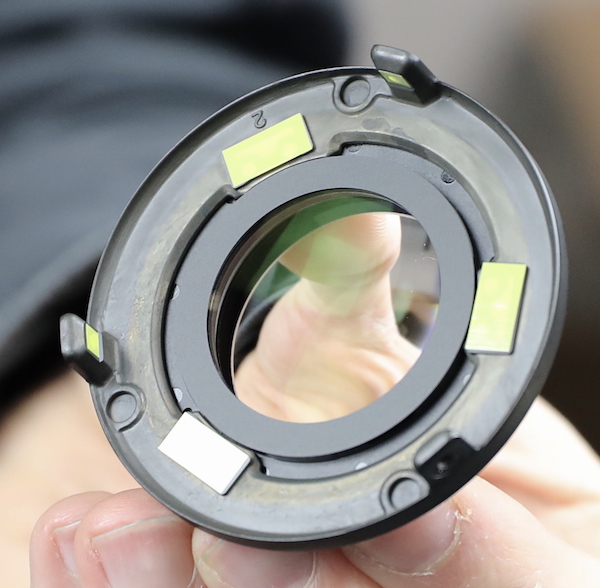
We had made better choices this time, mostly because we had already exhausted all the bad choices (a metaphor for my life, really). The zoom group came right out, complete with some compression springs and the untouched adjustment collars.
Lensrentals.com, 2020
This includes the aperture assembly we’d seen earlier.
Lensrentals.com, 2020
Now that it is removed, we can see it’s not a secondary aperture with the electronic aperture behind, as we thought earlier. This is the main aperture and a combination electrical/mechanical device. As we saw earlier from the top, there’s a cam that goes into the zoom ring, mechanically closing the aperture as you zoom to maintain f/2.8.
Here’s a good shot of the adjustable collar for the mechanical aperture function (top center). This would be adjusted using an ‘occulter’ (basically a sized target) so the aperture is the proper diameter. There is also an electronic aperture control inside that makes the aperture even smaller if you stop the lens down — very elegant piece of engineering.
Lensrentals.com, 2020
This assembly is basically two parts with three compression springs pulling the aperture assembly (in the front) towards the zoom element (in the rear). Since each of these two parts has it’s own cams (the forceps are in the forward cam hole) we aren’t certain if the spring is there to provide better feel during zooming (unlikely), to provide pull on the mechanical aperture when un-zooming (possible), or for some reason we don’t understand (almost certainly).
Lensrentals.com, 2020
Now we go back, again remove the cams from the focusing group, and take it out through the front of the inner barrel.
Lensrentals.com, 2020
The inner barrel is now empty, other than a few cams and the various flexes passing hither and yon.
Lensrentals.com, 2020
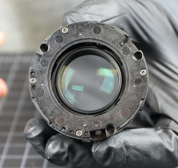
The focusing group is self-contained. The rear view of the assembly shows just the backplate and the four screws holding it together.
Lensrentals.com, 2020
The front view showed the paired stepper motors that move the focusing group, and the two flexes that power them.
Lensrentals.com, 2020
Here’s a side view of one of the motors along with a position sensor.
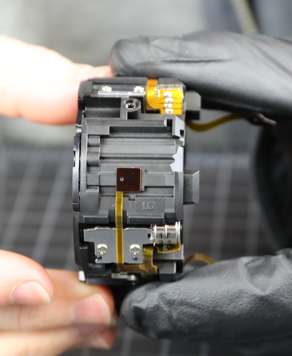
Lensrentals.com, 2020
As you can tell from the screws over the motors and on the backplate, this unit can be further disassembled. But we didn’t see what more information we’d obtain, and this disassembly had already been one of the longest ever. Entirely our fault, now that we know the right way in it could be done in a couple of hours, tops. But it had been a long day nonetheless.
So long, in fact, that Aaron left things out to put back together tomorrow.
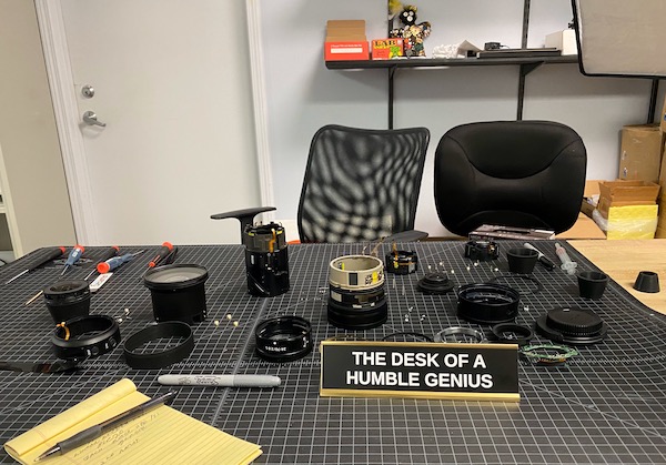
Lensrentals.com, 2020
Conclusions
As you can probably tell from our struggles doing this disassembly, the Nikon Z lenses are very different than their legacy lenses. They’re also different than what we’ve seen from other manufacturers. That suggests Nikon Z lenses, like Canon R lenses, are a completely new optomechanical design, probably done entirely in-house.
The engineering itself is incredible in most ways. The neatly laid out and solidly adhered flexes reflect the careful design. The taping of every possible point that Loctite or anything else could get in the lens does, too. The design is logical and clean; the difficulties in the tear-down were ours. Now that we know our way around, disassembly won’t be bad at all.
I will complain about the fact that filter-ring or hood-slot damage means an expensive repair. That was not well thought out; those are common repairs, and they’re going to be pricey on this lens. But the lens is well-engineered, and I see no other weak points to make me think it will be anything less than reliable.
I’m sure various internet experts have strong opinions about stepper motors versus electromagnetic motors versus piezo motors for linear focusing. I don’t have enough knowledge to comment other than the vague general understanding that EM is probably the fastest and stepper perhaps more accurate. I would simply caution people that taking engineering reports of how well a given motor does this or that may not be very well reflected in how a lens performs autofocus. Autofocus, like lens disassembly, is a complicated profession.

Roger Cicala and Aaron Closz
Lensrentals.com
January 2020
Author: Roger Cicala
I’m Roger and I am the founder of Lensrentals.com. Hailed as one of the optic nerds here, I enjoy shooting collimated light through 30X microscope objectives in my spare time. When I do take real pictures I like using something different: a Medium format, or Pentax K1, or a Sony RX1R.
-
Brandon Dube
-
Henry Winokur
-
Ben Langlotz ?????
-
Jim Huang
-
Michael – Visual Pursuit
-
Roger Cicala
-
PhilK
-
Michael
-
Eamon Hickey
-
Akvinat
-
Akvinat
-
Dimy
-
Athanasius Kirchner
-
Roger Cicala
-
Roger Cicala
-
Athanasius Kirchner
-
Athanasius Kirchner
-
Athanasius Kirchner
-
Athanasius Kirchner
-
Athanasius Kirchner
-
Roger Cicala
-
Larry Huck
-
PhilK
-
PhilK
-
PhilK
-
MyrddinWilt
-
geekyrocketguy
-
DrJon
-
Tord55
-
Jim Huang
