Looking at Clear and UV Filter Spectrograms
I’ll start by saying, this is not an article – or at least not a complete one. When I wrote My Not Quite Complete Protective Filter Article, I promised to try to add transmission spectrograms so that you could see not just the wavelength I tested for transmission, but also how the rest of the light wavelengths were transmitted. So this is just an addendum to that article. If you haven’t read that, then please don’t read this until you have.
Mainly I was interested in how much difference there might be in the color cast of the various filters. I’m not numerically quantitating that here, but looking at the graphs, you can probably tell if one passes red light more easily than green or blue and therefore seems warmer, etc.
I honestly could care less about how well any of these block UV light. But many of these are called UV filters so it seemed like we should check the UV part, so I ran the spectra down into UV range so both of you who are interested in that can see it.
A couple of points though:
- We very accurately measured transmission at a 635nm wavelength (red light) using a laser in the previous blog post. The spectrometer as we did this test is NOT as accurate for absolute transmission value, so don’t look at a graph and say “oh, well the spectrogram said it was 99.8%, and this looks like 97%.” If you do that we’ll know you can’t read and won’t take you seriously.
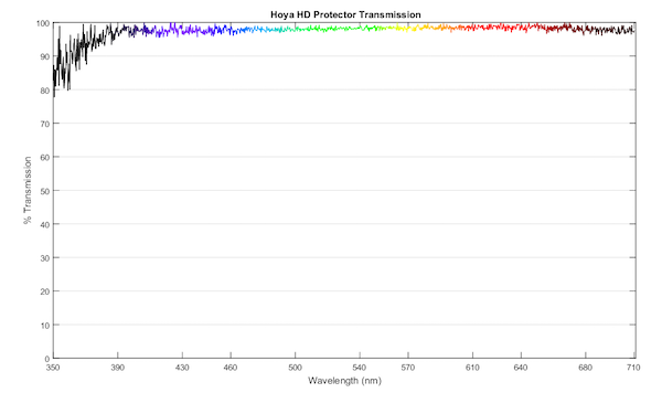
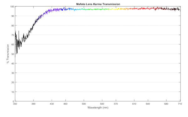
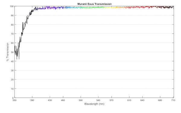
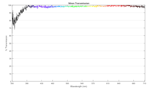
- Each spectrogram is quite accurate for relative color. So you can see that a given filter passes more light at certain wavelengths than others. You say filter X passes green light better and filter Y blocks more blue light. But you can’t say filter X passes 98.5% of green light, and filter Y passes 97.6%. This is all about the overall color cast of the filters and not about absolutes.
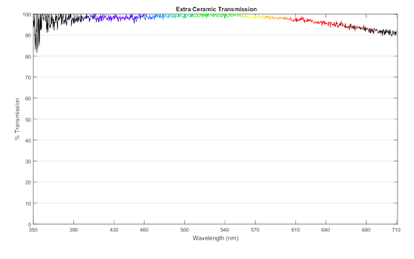
So without further ado, here are the spectrograms. Oh, there is one ado. If you notice that a filter from the first article is missing from this article, you may assume that I broke it between then and now. Sometimes science requires sacrifice. Also, I’ve thrown in a couple of ceramic filters, brand not listed because they were loaned to me as a favor so that you can see the ceramic spectrum.
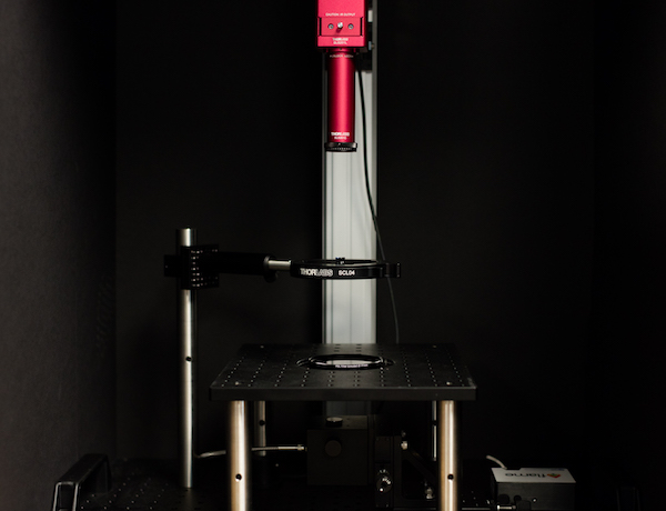
Oh, and to give credit where it’s due: Brandon designed the spectrometer using Thor-labs components that kept things somewhat affordable, Markus and Max wrote the software to make the pretty graphs, and Aaron and I did the testing. And made the blackout box, which was like having kindergarten flashbacks and making a cardboard-box fort.
Filter Spectra in Alphabetical Order
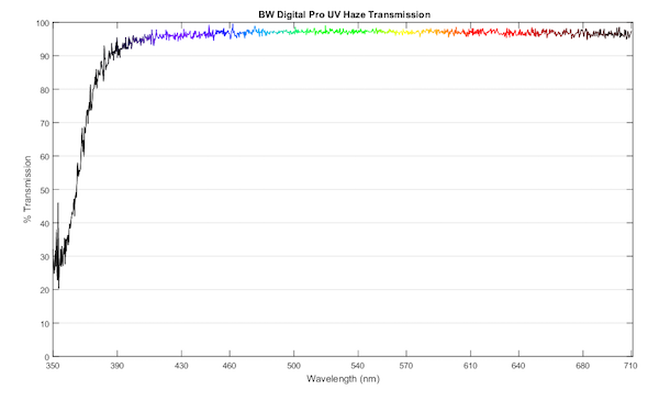
B&W Digital Pro UV Haze
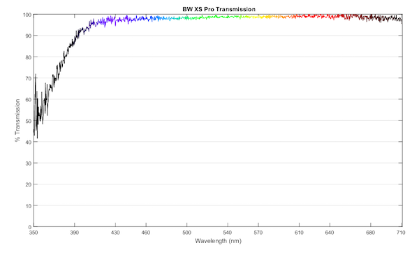
BW XS-Pro Clear MRC-Nano Coated
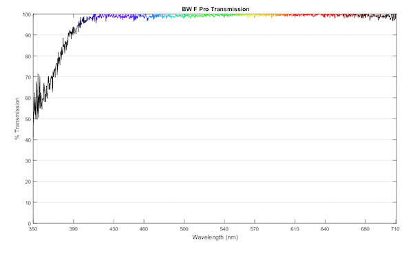
BW F Pro Clear MRC
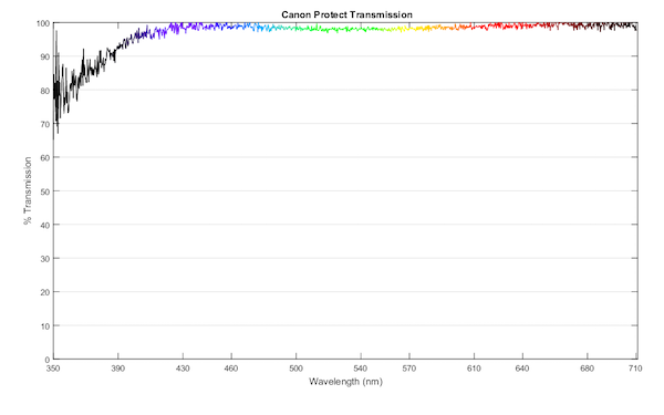
Canon Protect
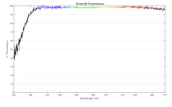
Chiaro 98
Ceramic – Extra Thick
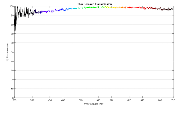
Ceramic – Thin
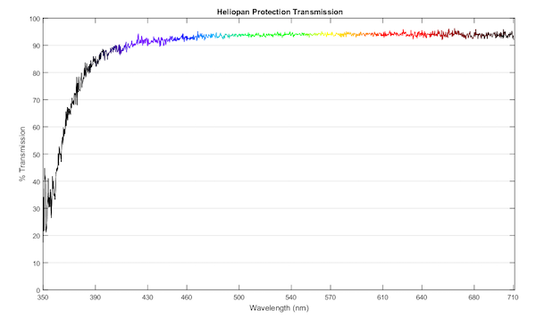
Heliopan Protection
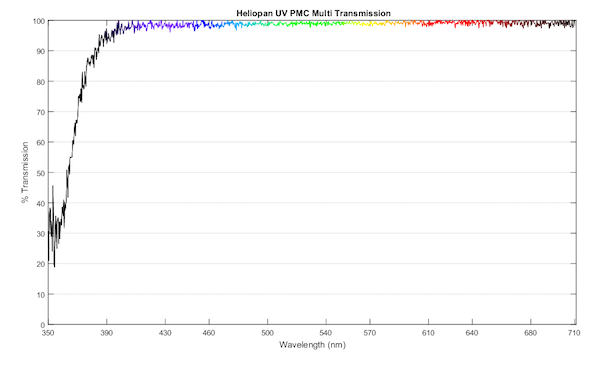
Heliopan UV SH-PMC Multi
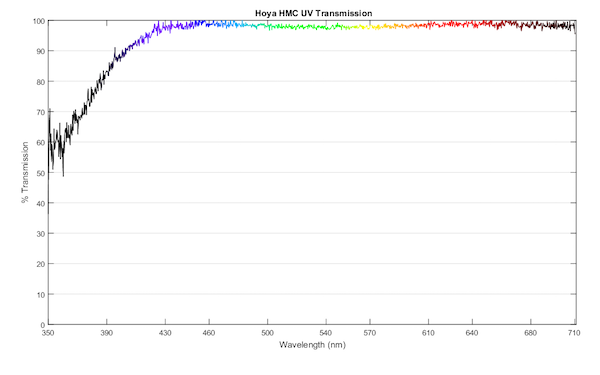
Hoya HMC Multicoated
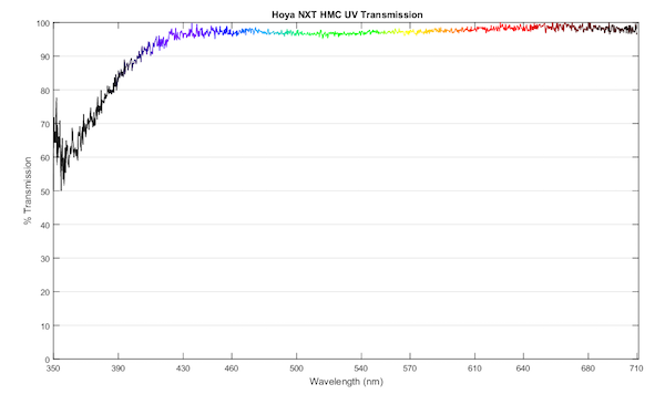
Hoya NXT HMC
Hoya HD Protect
Mefoto Lens Karma
Marumi Exus
Nikon Neutral Color
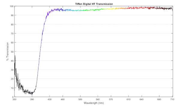
Tiffen Digital HT
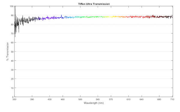
Tiffen Ultra
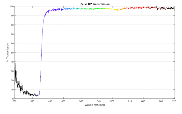
Zeiss T*
So, What Did We Learn Today?
Not a lot. The amount of UV filtering that goes on seems really rather random in the non-UV filters. As does the wavelength at which they start UV filtering and how quickly it drops off. The Zeiss T*, for example just removes everything. Some of the others just kind of meander down to removing some of the UV, as do some of the ‘clear’ filters. Some get further into the UV spectrum before they filter, while others start just on the visible side of UV. Maybe this matters to some of you. Probably not.
Most of the filters transmit a pretty flat spectrum in the visible range, although several, led by the Tiffen Digital, will have a distinctly warm cast. And in the very limited sample size we tested, ceramic filters might look cool, or not. So I guess we learned that same old lesson: white balance with your filter on, or shoot in raw, or both.
Max Bruggerman, Roger Cicala, Aaron Closz, Brandon Dube, Markus Rothacker
Lensrentals.com
September 2017
What is best in life, Roger?
To crush the marketing departments. See them driven before you. And to hear the lamentations of their sales reps.
42 Comments
Chik Sum ·
Hi Roger, may I ask if the Ceramic ones are the sigma ceramic filters? those looked nice on paper but seems not in real use
Roger Cicala ·
Chik, no they aren’t. They’re from a specialty company doing me a favor.
donpedro ·
Hello Roger,
I have a small quality of life idea for graphs like these: would it be possible to add lines that mark the edges of the visible light spectrum when you generate graphs like these? With the Zeiss T*, for example, I can’t really tell if it’s a sharp cutoff just outside visible light, or if it takes a chunk of visible blue with it. Thanks!
patish ·
I’m going to make a guess here, not being an optical expert, but where the graph changes from color to black marks the edge of the visible light spectrum. So, the Zeiss does indeed cut off a small (because of the steep drop) portion of the visible blue. Close, Roger?
Brandon Dube ·
The line is coded in a spectral color map. It becomes black outside the visible range.
Athanasius Kirchner ·
+1. Good suggestion.
macona ·
400-700 is considered visible light, though at 700 its getting pretty dark red.
Petrochemist ·
The actual wavelengths visible to humans varies quite widely (even if ignoring colorblindness).
I can just about see through a 950nm filter that has no measurable transmission throughout the 300-750nm range. (The quoted wavelength on these filters is roughly the 50% transmission wavelength, most longpass ones are fairly sharp cut off, but still show trace transmission quite a way below their ‘cut-off’)
At the other extreme, young people can often see further into the UV than older people. My own blue/violet response changed significantly when trace cataracts were removed – for a while (til my brains AWB adjusted) my treated eye gave much bluer vision than the untreated one.
Pedro Aphalo ·
Hello Roger,
At wavelengths shorter than 380 nm there seems to be quite a bit of stray light in the spectra. This Is most noticeable in the Zeiss T* plot. The increase in apparent transmittance towards shorter wavelengths is a measuring artefact. This does not change any of the conclussions, but without realizing this, the plot may look surprising to some of your readers.
Answering to the other Pedro, the 400 nm boundary is just a convention. The ISO standard definition of visible light extendes into the UVA region. In addition different cameras will “see” different amounts of radiation of wavelegths shorter than 400 nm.
Brandon Dube ·
<380nm isn't stray light, it's noise because of the shape of the source spectrum and the limited dynamic range of the spectrophotometer at the core of this instrument. If we stitched exposures for UV~VIS~IR, things would be better.
Pedro Aphalo ·
Thanks for the clarification! Yes, either can be the cause depending on the spectrometer and light source. I you can get rid of it by bracketing the integration time, then I was definitely wrong. Some of our Ocean Optics spectrometers do really suffer from stray light by IR being detected as UV, when the light source emits enough in the IR.
Steven Dean ·
Do you have a source for OO spectrometers detecting IR as UV?
Pedro Aphalo ·
I am not sure what you mean. I guess supplier. Ocean Optics sells directly in addition to having distributors. Most array spectrometers can be configured with different gratings. In most cases the boundaries of what is possible are given by the sensitivity of the detector. So IR in my earlier message should have been NIR (near infrared). For longer wavelengths different array detectors are used.
Piotr Krochmal ·
Hi, Thanks for that test. But Roger, as you wrote some times ago transmission is not the only issue with filters. Reflections are biggest problem. As you wrote we can make WB balance or even better Color balance by X-rite in PS- LR enviroment. But IMHO biggest disadvantage using filters are reflections.
Roger Cicala ·
Piotr, with a clear or UV filter (no a polarizer or ND) we can assume what is not transmitted is reflected.
Piotr Krochmal ·
True. But reflection/transmission is “light angle dependable”. If you make measurements only with straight angle it give us best possible transmission. That data will work great for super telephoto lens. So question is could you make some tests with different ray angle? 90(we have those), 60 45 and 30 and even 15?
Olivier ·
>But reflection/transmission is “light angle dependable”.
Yes that was also my question.
Also, modern lens and sensor already blocked the UV so a UV fillter is useless.
No ?
Ilya Zakharevich ·
??? You can see that this is definitely not true in UV; so why do you think it would hold in visible?
Roger Cicala ·
Ilya, I’m not sure I follow. The coating (on those filters blocking UV) are designed to absorb that wavelength. But all of these have coatings designed to improve transmission of visible light.
Ilya Zakharevich ·
First of all, I did not realize that it is the coating which filters the UV. I thought it is a layer of some substrate which is not fully transparent in UV (as opposed to coatings which AFAIU work via interference). IF it is coating, this makes it much easier to agree with you.
However, I still have my doubts: are you SURE that this is done via interference? (My doubt is based on ignorance: I do not know how to design such coating.)
And: if it is not coating, then we know that the layer I mentioned above absorbs significant amount (30–70%) of light at some wavelength. Which implies that one should not be surprised if it absorbs measurable amount of light at other wavelengths too (at least as my understanding of physics of absorption goes).
Pedro Aphalo ·
In principle one cannot separate absorptance from reflectance with a transmittance measurement. However, reflectance from an uncoated glass is around 8 to 10%. In regions where transmittance is relatively low (high absorptance) I think it is most likely that the predominant cause of low transmittance is absorption by the glass substrate, but I may be wrong. On the other hand there is no reason for using a glass that would absorb in the visible region. Not all filters are made equal, and for example some very old coloured filters for black and white photography where made as a sandwich of two clear optical glass disks with the actual coloured layer as “filling” absorbing at a certain range of wavelengths. Interference filters are in general more expensive to make, being some Baader filters a good example. Even if the coating is what attenuates UV, it does not need to do this via reflection. Schott has an on-line filter calculator at https://www.pgo-online.com/intl/schott-filter-calculation/schott-color-glass-filter-calculator.html which can output the total transmittance spectrum (taking into account reflections) or internal transmittance spectrum (discounting the effect of reflections) for any of the glass types they make for use in filters. One can also set the desired thickness of the glass. The simulations are for just the glass with no coating. You can try GG395 and 1 mm thickness as representative of a typical UV filter. GG420 looks very much like Zeiss UV T*.
Mike Earussi ·
That was the question I wanted to ask. Can we assume that the higher the transmission the less likely there is of any reflections?
Joel Eade ·
How did we come to the term “ultra” violet and “infra” red? Looking at the wavelengths it would be more intuitive to go with Infra-Violet and Ultra-Red.
Alexis Mackintosh ·
The terms ultra means above, while infra means below, thus above violet (shorter wavelength and higher energy than violet light) and below red (longer wavelength and lower energy than red light).
Joel Eade ·
It was the energy part I did not understand. It seemed to me shorter wavelengths would be infra… and longer would be ultra…
Alexis Mackintosh ·
Yes, it is a bit confusing, the relationship between
Energy and wavelength is inversely proportional. the equation being:
E=ch/Lambda
where E =energy of photon, Lambda = Wavelength, c= speed of light and h = Plank’s constant
Athanasius Kirchner ·
Conclusion: I’d take the Heliopan UV multi if I had to. Seems like the only one that doesn’t affect colors and filters most of the UV rays.
But of course, UV filters are for people who like getting scammed. And before you yell “BUT, BUT, BUT MUD AND WATER AND DUST!!1!”, use an el cheapo filter and pray. Or even better, just take a beater camera and lens, because a little piece of glass in front will do squat to protect all of the other 20,000 moving parts and gaps on the camera and lens 😀
Mike Earussi ·
Roger, I just to add my thanks for this article. You’ve provided the first solid information to help differentiate the various coatings from the various manufactures, since in the past what we’ve mostly had was just their PR. Especially with the B+W your tests really show the superiority of their MRC coating over their earlier one, and even over Hoya’s HMC. How much of this is visible in real life I don’t know, but it is nice to finally know what I’m actually buying.
Nate Patterson ·
Cicala the Cimmerian!
denneboom ·
There are also some discussions online about a stong uv filter(2A) that removes purple fringing from photos. thats the only reason i would but a uv filter on a lens. But id rather buy a lens that doest give fringing in the first place
alek_komarnitsky ·
I especially enjoyed this article Roger (and Brandon) since after having cataract surgery, I can actually see a bit into the UV spectrum – read more at http://www.komar.org/faq/colorado-cataract-surgery-crystalens/ultra-violet-color-glow/ – scroll down to see some fun testing with a Oriel Instruments MS 257 Monochromator … 😉
The 77mm Canon lens pictured on my website (in the simulation) is a “UV Haze (Sharp Cut)” … so I presume it has a drop-off somewhat similar to the Zeiss. I also “observe” this myself doing stupid geek tricks like shine a 365nm UV flashlight through it. For me, the brightness is attenuated quite a bit … whereas for “normal” people, they don’t see any difference. Another stupid geek tricks including looking at natural gas on my stovetop where the deep purple(UV) is attenuated with the UV filter whereas again, normal people say no difference. Scroll down to see a Canon body cap sacrificed to make a make-shift visible-light filter using Woods Glass.
Bummer I don’t live next to you as I’d love to volunteer to be a UV test candidate! 😉
Alek Komarnitsky ·
I especially enjoyed this article Roger (and Brandon) since after having cataract surgery, I can actually see a bit into the UV spectrum - read more at http://www.komar.org/faq/co... - scroll down to see some fun testing with a Oriel Instruments MS 257 Monochromator ... ;-)
The 77mm Canon lens pictured on my website (in the simulation) is a "UV Haze (Sharp Cut)" ... so I presume it has a drop-off somewhat similar to the Zeiss. I also "observe" this myself doing stupid geek tricks like shine a 365nm UV flashlight through it. For me, the brightness is attenuated quite a bit ... whereas for "normal" people, they don't see any difference. Another stupid geek tricks including looking at natural gas on my stovetop where the deep purple(UV) is attenuated with the UV filter whereas again, normal people say no difference. Scroll down to see a Canon body cap sacrificed to make a make-shift visible-light filter using Woods Glass.
Bummer I don't live next to you as I'd love to volunteer to be a UV test candidate! ;-)
David Bateman ·
Thank you for these curves!
The tiffen HT and Zeiss look to be the only filters that actually filter uv. The others just look like the typical glass transmission in uv spectrum. The ceramic is very interesting as looks to allow a lot of useful uv light through. This may be a cheaper option for uv lenses, as quartz lenses are very expensive. I have two 3 element lenses which are good for uv work with the baader venus 2 filter. I can’t afford the quartz lenses.
For uv filtering, this can be useful to avoid the purple blobs with Olympus cameras. From my limited tests, the Olympus cameras have very weak uv filtration on the sensor, almost none. My Panasonic GM5 does not let any uv through. Thus sun flare and purple fringing is different between Olympus and Panasonic cameras, not just software correction.
macona ·
What lens are you using for UV? An enlarger lens? I had my 5DII modified with a quartz window in place of the IR-Cut so I can use it full spectrum and would like to try UV. I also have a Quantix cooled 6MP camera that has a bare CCD in a vacuum chamber with a quartz window that is sensitive to pretty deep in the UV that would be interesting to try.
David Bateman ·
Check out:
https://kolarivision.com/uv-photography-lens-compatibility/
For some affordable uv lenses.
I have a tmount 35mm f3.5 unknown lens, may be a Kuribayashi.
Also have a m42 mount Steinheil 50mm F/2.8.
My pentacon six Zeiss 80mm f 2.8 also seems to let a usable amount of UV, as does my Yus 135mm f2.8.
I use a baader venus 48mm filter, so my peak is about 350nm.
macona ·
Dang, $387 for that filter. I need to get my e-beam system going so I can make my own filters.
David Bateman ·
To get started you can pick up one of these:
https://m.ebay.com/itm/Kyoei-Kuribayashi-T-Mount-Variant-35mm-F3-5-Lens-Filter-Set-UV-Photography-/272557822799
The filter combo seems ok from review on uv forum.
mijami ·
Given that filters are so thin and lenses are so thick, I wonder if filter transmission makes any difference at all in the real world. Lens manufacturers infer that all their lenses are all color balanced but it would be interesting to see spectrograms on some of them.
Brandon Dube ·
If the transmission is poor, the addition of a filter will cause a lot of flare in images.
The bench that makes these measurements can do imaging optics too. Lens specta are forthcoming.
Volker Bartheld ·
Haha. Roger uses the famous Schwarzenegger quote from “Conan the Barbarian (http://www.imdb.com/title/tt0082198/quotes)!
Fun aside: What light source were you using? The Thorlabs SLS201L(/M)? Its spectral power distribution tells me, that it gets a lot (I mean: A LOT) dimmer beyond 400nm which might explain the wiggles in your diagram: There’s just much more noise recorded by the spectrometer.
In fact, it is not necessarily (only) the coating that blocks UV radiation as you can see on the diagram of this page: http://www.rothkegel.com/transmissionkurven_versc_glaeser.html. Typically, UV-A/B/C doesn’t make it through ordinary window or float glass (http://www.glasludwig.de/Download/gl006.pdf), you would need quartz/fused silica glass for that (https://www.pgo-online.com/de/kurven/quarzglas_transmission.html), which is used in most of the UV-C irradiation lamps e. g. for desinfection (Osram Puritec, Philips TUV).
If you want a steeper absorption edge, yeah, coatings come to the rescue. Fun fact: This is IIRC *NOT* the trick to avoid Ozone generation in UV-C lamps. Instead, they are doped with Amalgam to cut off the 185nm mercury emission line (http://www.osram.lampen-raum.de/media/files/pdfKataloge/OS_SP.pdf).
The curves you’re showing don’t convince me yet that the effect is necessarily due to a coating, even though there most likely is one to improve transmission in the visible spectrum. Look at what Hoya has to offer with their R72 IR filter: http://www.hoyafilter.com/hoya/products/specialeffectsfilters/r72infrared/.
Having said that: Thanks for to awesome review! Seems that the Hoya HD Protector isn’t terribly bad after all. And it is supposed to have “Chemically Enhanced Optical Glass [which] is 4x Stronger”. And stronger means better for a protection filter, doesn’t it? 😉
Brandon Dube ·
We use a color balancing filter with the source (you got the model # right) to even out the spectrum in VIS/UV, but it is still considerably weaker at e.g. 360nm than at 500nm.
The loss of transmission from glass into the UV is relatively smooth/slow, a high Q/sharp cut will always be beacuse of coatings. The Canon protect filter is pretty representative of normal glass for UV filtration.
A glass model (e.g. sellmeier) can predict the loss of transmission in UV from the (complex) refractive index as a function of wavelength. The imaginary component turns directly into the ‘a’ value for Beer’s law in propagation thru a medium.
Fink ·
Again, the above measures are valid as far as they go. I’d like to see measurements from 10 or even 20 filters marked the same…be that from Hoya or Tiffen or anybody. That will get to the root of manufacturing consistency. Until than, the above measure should be considered ‘artifacts’. It would help if you could look at the quality program of each maker, with an eye towards looking a the control chart of in-line measureables. I’d only be guessing as to the number of measureables and what they are. And as to control limits? And other process variables?