We spend a lot of time fixing broken stuff. As sort of a side gig to that, we advise some manufacturers about what is likely to break or is regularly breaking. We offer our input to all manufacturers; some are interested in it, and some don’t give a flying damn. For free, we blog about it, too. Some people are interested; some just go “I had one, and it didn’t break.” We had hundreds of whatever, and most of those didn’t break either. But when 15-20 out of 100 breaks, as opposed to 1 out of 100, we tend to look for why.
Most electronics (as opposed to optics) manufacturers design their product and outsource the manufacturing to the lowest bidder. Manufacturing costs for the circuit board, chips, and cases are pretty inconsequential; what you’re paying for is the smart ideas, the software/firmware, and circuitry it runs on.
Very, very few of the electronics manufacturers actually have a service department. If you send something in for repair, they replace it with a new one (although they may call it refurbished), either under warranty or for a repair fee. If the device has some expensive other components (usually an LCD or OLED screen), they may have a tech who pops the case open and replaces bad circuit boards. A lot of these devices don’t even have openable cases; the last step in manufacturing is gluing the two halves of the case together.
Why do you care? I mean, if they’re going to replace it under warranty, what’s the difference? No difference, except the keyword in that last sentence is “if.” Warranties run out, and with most of these devices, you’ll have to buy a new one if it gets damaged after that. Sometimes, profits start falling and suddenly ‘user damage; warranty void’ takes the place of ‘replaced under warranty.’
When the selling company doesn’t care about construction (they are software/electronics people, after all), you get some fragile stuff being manufactured. That is the way of the world now, and I understand that – I live with it more than you, I promise. When the company stops replacing damaged items, we start opening the broken ones to see if we can repair them ourselves.
One thing that’s just about guaranteed to fail on every electronic device is side-mount buttons and side-mount I/O ports. When we stock products with such buttons, we just assume they’re all going to break. The whole purpose of this post is so you can make that same assumption.
What Do You Mean By Side Mount Buttons?
Electronic devices come in all kinds of shapes. One of the popular shapes is like a large deck of cards; a flat cuboid (flat box). If the device shape is a flat box, you can be pretty sure the circuit board inside fills up the bottom of the box. There’s probably at least an on-off button communicating with the electronics. There are two ways to mount the button; on top, pushing it down toward the circuit board, or on the edge of the circuit board, pushing from the side. What’s the difference? Well, lots.
Let’s make a schematic of a small electronic device with on-off buttons. The button can be on the edge of the board, pushed in from the side of the device, or in the middle of the board, pushed down from the top.

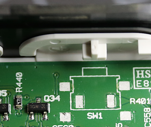
Notice the switch has little wire legs that are attached to the circuit board because electrons are flowing and all. They’re just wires soldered to the circuits on the board, but in addition to serving as your electron highway, they are also the only thing that holds the switch on the board in 95% of these devices.
What does it look like in real life? Here’s a top view of a typical side switch; you push the switch, and the piece of plastic pushes the button that’s part of the switch.
Lots of devices have side switches.
Nowadays, where tiny little robotic elves make all circuit boards, they’re all flush soldered to the top of the board. Wait, not all. Some are just stuck onto the board with conductive glue. Conductive glue is an excellent conductor, but a not very good glue.
So anyway, all that’s holding the switch in place is a tiny amount (robots are very efficient) of solder or glue. To simplify things, if you push down on a switch, you help the solder or glue do its job; you’re pressing the switch down into the place it should be. If you push a side switch, you apply shear forces directly across the soldered/glued joint.
Now is where you say, “But surely the manufacturer has put some braces and things on that switch so you can’t just rip it off the circuit board.” And where I say, “Why would you think that? Did you see any brace in that picture above?”
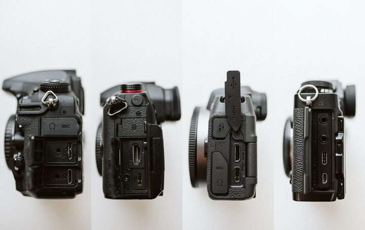
Let’s look at the opposite of a push-button; some I/O ports.
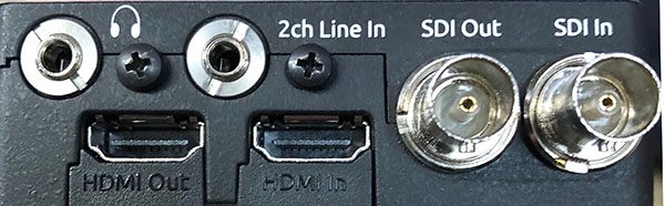
This device has six I/O ports side-mounted. If you glance at it, you’ll see the two SDI ports on the right side, and the two mic jacks on the top have all have bolts holding them to the side of the case. They aren’t going anywhere.
The HDMI ports, though, are soldered to the circuit board and poke out through a hole in the side. In theory, of course, you don’t put as much pressure inserting or removing and HDMI cable. Theory, however, never broke down the set at the end of a shoot; minimum-wage gaffers do that. They are as gentle and delicate as a fart in a sports car.
This should illustrate why I’ve never seen an SDI or mic jacks pulled out of the circuit board on this device, but I have seen some HDMI ports torn off the circuit board.
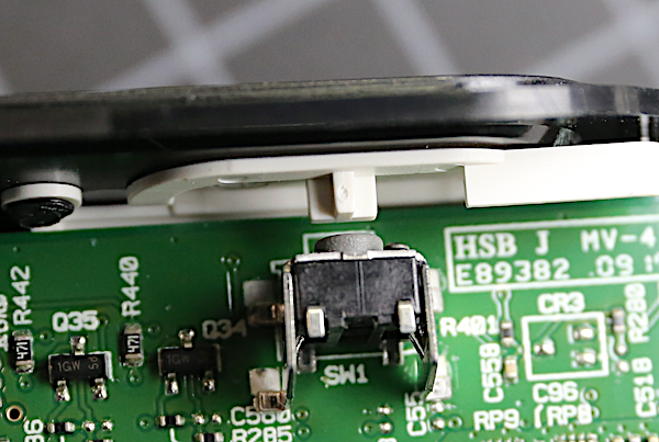
Back to my push buttons, though, there’s usually something holding the button in place. How much something? If you haven’t looked inside, you have no idea, but it rarely is what you’d call robust. Here’s a close up of a typical side-mount push button. The clear plastic piece is a light guide; the feet sit over LEDs surface mounted to the circuit board and carry the light up to make the button glow when the device is on.
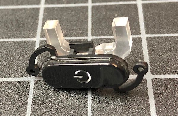
The two black plastic wings on either side hold the button in place, both providing that springy feel but also keeping you from shoving it too far. I don’t have the test equipment to tell you their breaking point in Newtons, but I can tell you that you can put one under your fingernail, snap it like a twig, and never feel it.
If you flip the button over, that light guide is held in place by an even thinner bit of plastic that it snaps into. I have been unable to break that piece by just looking at it, but I can assure you anything other than looking at it will break it. (The top that you see is about four times thicker than the depth, which we measured at under 0.2mm.)
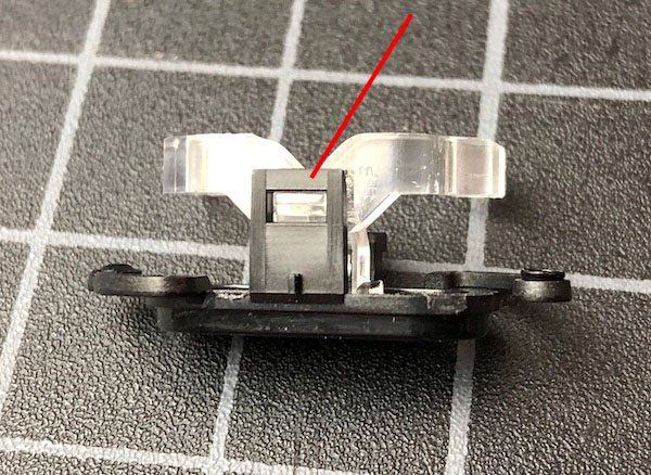
So what happens if you push the switch frequently, or a bit too hard and bend or break the plastic retainers? Well if you scroll back up to the picture above, you’ll see that nothing holds the electrical switch on the circuit board but the solder it was put on with. The solder is not strong, and the metal traces on the circuit board itself are even weaker. So this is what things look like after a too-hard push or the retaining springs weaken. Oops.
In this case, the switch was utterly free, rattling about the case. Sometimes they just bent up off of their traces; they don’t rattle, but they don’t turn on either. While this is most common with on-off buttons, it’s also a reasonably frequent event with HDMI and micro-USB ports. Don’t get me wrong; reasonably frequently for us means 6 or 8 out of 100 devices per year. If you have one, it will probably last years before a switch breaks, as long as you’re reasonably gentle.
For those of you who wonder why we don’t just resolder the switches to the boards, it’s not that simple. Robotically assembled boards use precision solder that is difficult-to-impossible to resolder by hand. In most cases, even if we could spot solder, the boards conducting traces were damaged when the switch pulled off, and the board still needs to be replaced.
So Why Bother to Tell Us?
Mostly, this article is a warning. Don’t repeatedly push side switches, and don’t push them hard. They don’t give a lot of tactile feedback, so you may be tempted to push too hard. This can be worse with some devices that take a second or two to power up after you push the on-off button; people tend to push again harder during that second or two.
Also be gentle with cables in your USB micro or HDMI ports, too. Yanking them out seems to be the biggest problem here, but you can break off a port by forcing a cable in, also.
If you’re deciding between a couple of devices and one has a push-down switch, as opposed to a side switch, I would recommend going that route if everything else is equal. Again, it’s not a huge deal, but as best I can tell, a side switch is at least five times more likely to fail than a push-down switch, probably more.
Sometimes it’s hard to tell, just looking at a device if a switch is on the side of the circuit board or not. The shape of the device is a giveaway for smaller devices, but not always for larger ones. In those cases, a row of switches or I/O ports (or both) is a good hint. If they’re putting switches on a side mount, they’ll probably line them up in a row.
Most importantly, don’t just ask the manufacturer what their repair policy is; check online to see if other consumers have some experience with it. Saying ‘5-year warranty’ doesn’t matter if they’re going to call all switch failures abuse or misuse. Some companies put existing customer service first; others are more interested in marketing to get a zillion new customers.
Roger Cicala and Aaron Closz
Lensrentals.com
August 2019

30 Comments
KeithB ·
One of the first things I learned in the early 70’s when I started this stuff was “Solder is not a mechanical connection, it is an electrical connection.”
geekyrocketguy ·
The side-mounted submini audio jack on my Syrp Genie Mini was broken by some rough handling when a cable was plugged into it. I emailed the company and was shocked when they said they would mail (from New Zealand to the US!) a new audio jack. The Genie wasn’t under warranty, but they did it for free anyway. I unsoldered the old one, soldered on the new one, and it worked again. This is a rare success story–as Roger said, I was expecting that Syrp would have outsourced their manufacturing and wouldn’t have individual components sitting around.
I also keep a pile of microswitches of various sizes in my closet and have repaired various things with them–most recently the power button of my desktop computer.
Speed ·
Which is why I just threw my headphones away. The micro USB connector used for charging came loose and charged no more.
J.L. Williams ·
In addition to the connector pulling off the PCB, another thing I’ve had happen a lot is for the little plastic tab inside the connector to break off. This tab is what carries the actual contacts, so if it breaks you’ll need to replace the whole connector (which, as Roger just explained, generally means replacing an entire board.) Micro-USB connectors seem to be the worst offenders, and I’ve broken these just by wiggling a plug slightly or forcing it in at a slight angle. Yes, I’m clumsy, but maybe you are too…
Ed Magowan ·
More than once I’ve used hot glue to provide support to side mounted switches.
Roger Cicala ·
Yes sir! I’ve also taken pieces of plastic and glued a brace in place.
Dave Hachey ·
“Hot glue” = “Hot snot”. I hate this stuff.
Andre Yew ·
These are all good observations, but sometimes side switches are mounted on their own dedicated board that’s parallel to the surface the buttons are on, so they are essentially push-down switches. It’s not easy to tell if this is the case without opening up the device though. This is also more expensive to produce, and has different failure points (like the cable that has to connect the switch board to the main board) and compromises.
Some side switches also have one or more little feet go through the circuit board to mechanically reinforce the switch, but I’ve seen those broken too. I guess the physics are really against small switches: push something small hard and/or long enough, and it will break.
Roger Cicala ·
Andre, good point. And while you can’t tell for sure, usually sub-boards are in larger devices, like video cameras.
GulliNL ·
Do you have any examples of over-engineered devices where a company would go out of their way to fortify these switches?
I could imagine placing a strut behind a switch to keep it in place, or perhaps a button design that would hit a barrier preventing it physically from exerting large forces on the switch underneath it? For instance (aside from being a different kind of side switch) iPhones with side mounted power buttons have the switches screwed in place on the chassis (step 40 in this guide; iFixit guide for power button replacement)
I would hope that some devices designed for professional use (and priced likewise) could take more of a beating.
ipdouglas ·
I treat everything I own with kid gloves, I keep boxes and leaflets etc. Not just photographic gear. This way I minimise breakages and often are able to resell when upgrading items that can look as new to the delight of the new owner. However I have seem endless clumsy people battering quite delicate optical, electrical and mechanical items for no good reason! This is more common if the person does not pay for it if it breaks (hands up here pros) (yes I know pros buy their gear but it is written off in business costs and costs to a client so technically they dont).
You only have to look at the state of vehicles driven by employees to see how people treat items when damage is a carefree non-expense.
Ciaran ·
It’s possible but you need specialized equipment and materials. The way we do it in our prototyping lab is to place little blobs of solder paste on the pads with a micro syringe and carefully place the component down on the solder paste with tweezers. This is done under a stereo microscope by a tech with steady hands. The solder paste is sticky and holds the component in place while the soldering is done. The whole board is suspended over an infrared heat source that brings it close to the melting point of solder. Then an infrared wand is used to direct a focused beam of IR on the actual component, heating it to the point were the solder paste melts and reflows. The surface tension of the molten solder usually pulls the component into alignment with the pads if it is off a little in its placement. Then the heat sources are turned off. Any broken connections on the PC board have to be carefully fixed with fly-wires – very thin wires to jumper the broken connection to the next accessible point on the same net where it can be soldered down. A dab of epoxy helps keep the damaged component from getting loose again.
All this is harder than the old solder with a soldering iron techniques, but it’s often easier for us than rebuilding a whole new prototype board from scratch. It may also be useful if a replacement board is not readily available or is very expensive. I’ve fixed a few of my own gizmos this way.
Ciaran ·
P.S. The same technique with the IR heater and IR wand can be used to safely remove a damaged component from the board.
Roger Cicala ·
You have skills and toys I don’t have, but that’s good to know that it’s at least possible.
Ourgon ·
You don't need fancy stuff like IR wands et al, just get a hot-air reflow station (I got an Aoyue 968+ off Taobao a few years ago for less than €100, these things don't have to break the bank) and you're set. I've used this to repair anything from broken sensors on cameras (Canon, I'm looking at you) to LCD controller boards on laptops and monitors.
almeich ·
I really don’t know if you meant tools or toys. Anyway, it made my day. Or part of it.
Roger Cicala ·
Tools are my toys. Your talking to a man who is deeply passionate about certain brands of screwdrivers 🙂
Dave Hachey ·
Nice article. Much of the consumer electronics we have is just crap. If you want to see elegance, watch some of the Youtube videos on teardown of the old HP and Keithley test gear. “A thing of beauty is a joy forever.”
John Merlin Williams ·
Maybe it goes without saying – ditto camera connector ports. In my (limited) experience, many/most I/O ports on cameras are soldered-on side-mounted to the PC board. When disconnecting those snug-fitting teeny-weeny HDMI and USB connectors my instinct is to wiggle the cable free but have learned that this multiplies the sheer stress on the solder joints. Strain relief brackets help keep an attached cable from stressing the connector port, but you still have to exercise caution when disconnecting the plug itself. My only solution has been to “pinch” the connector as close to the port and leverage it straight out using my fingernails as a sort of fulcrum. Any other suggestions for cable removal?
Thomas ·
Would be interesting to see some statistics about defects with models and brand.
Roger Cicala ·
Thomas it’s always a slippery slope. Our usual protocol is to notify a manufacturer and if they are receptive give them time to fix it. Being too public has often entrenched them into an ‘it’s fine as it is, there is not problem’ position. I generally give them an opportunity to fix things before I call them out.
The other thing here is we’re talking about a low frequency; maybe 5% a year compared to 1% a year if everything is good. Unless I have hundreds of the item in question, it’s hard for me to be statistically certain one is worse than the other. If I group all side buttons or ports together I have plenty of copies to be statistically significant; but then it’s not one manufacturer; it’s lots.
Siegfried ·
Uncle Roger,
there used to be some [Like] button on the right side of the blog. Or the left one. But I don’t see it anymore. Same thing, eh? Sorry if I broke it.
Yours,
Zig
Ashley Pomeroy ·
I remember that the old Fuji S3 Pro had a problem whereby the USB port on the side of the camera would often break off and rattle around inside the body. In fact if you google “fuji s3 usb port” the top results are some forum posts where people complain about the port. I owned one for a while – the image quality was lovely but it was one of those Frankenstein cameras built on the body of a film SLR, and it felt hollow.
In the audio world Behringer makes some pretty good budget gear, but the jack plugs and MIDI ports are usually attached directly to the circuit board without bracing, so I’m wary of repeatedly plugging things into them.
Apple gets a lot of stick, but their MagSafe connectors worked well and transferred the problem to the cable, which is easier to replace than the connector. The problem with a camera is having space for a cable tie.
ilLogict ·
Hi Roger.
Great article! However, note that on the picture with several I/O ports, the HDMI ports are actually attached to the enclosure, as the other ports. As the port design itself can’t have bolts, high-quality ports will have a flange (with a hole) that extend to the top, in which you can pass a screw though. That’s why you see a screw on top of the ports on your photo.
Molex HDMI socket reference 500254-1931 would be an example of that. It also has tabs that go though the PCB (which will have holes for that).
JosephAndrews ·
…love this blog.
After reading this post, I am wondering…
Even if the newish cameras have USB charging (where the battery is charged without removing it from the camera, admittedly a nice feature) via a micro-USB cable, does it make sense to recharge the battery the old-fashioned way (via its removal and insertion into the external charger)?
Are the mechanicals involved with batteries (doors and springs, etc.) more resistant to breakage than the USB ports of our devices (I have had problems with USB ports on laptops)?
…Knocking on wood now…going back to my Canon A2 (1995, I think), I’ve never had a mechanical problem with camera batteries, battery chargers, nor camera battery compartments and battery doors.
The occasional time I’ve had to use a USB cable on a camera/video device has been with Canon’s Elura video cameras…and the USB ports on those units were tight-tight-tight.
After thinking about this a bit…what would be great is if camera batteries could be charged wirelessly…in the way that newish cellphones (and my beloved Palm Pre) are charged wirelessly.
disqus_XN9vf0ShQK ·
Definitely. I hate that when companies don’t give you an external charger in the box anymore for small cameras. Just look at the size of the hinges and battery connectors – the battery is much more robust than a tiny micro-USB port for charging every day. And in the worst case, you can just tape over the battery door with gaffer’s tape…
That’s also why it’s almost always better to use a dedicated card reader to offload data than an USB cable (these micro-USB ports were especially prone to breaking, over the years I have had many card readers fail after repeated cable removal, but better than the camera port!). I don’t have the data, but I believe the newer memory cards like CF express with their broad connectors to be much more robust and rated for many more removal cycles than a micro-USB port (old CF cards were sometimes prone to bending the pins in camera, but it did not happen that much, since it had pretty tight tolerances in the camera slot guides – I think only about several times for me over a more than a decade with pro cameras and CF cards a pin actually broke, and that was with daily – and not very gentle – use).
SmithW6079 ·
It seems so obvious when you lay it out like this, but not automatically intuitive until you open something up. And things don’t always open without breaking. I leaned about just what you describe the hard way years ago with baby monitors. Needless to say we were very careful with the replacement. This is an excellent reminder for all electronic and camera gear. Thanks.
r k ·
Roger, I am curious which companies are receptive to feedback and which are not?
Eric Krouse ·
@@roger_cicala:disqus This post has put the fear in me; I’m a Fuji shooter (X-T3’s) with more video clients than stills these days. External battery packs are all but required. What is your opinion on the newer crop of magnetic adapters for USB devices? Anything inside these modern cameras that would get ripped over to the left if a magnetic cable link were used? Thanks!
Roger Cicala ·
Eric, I don’t have any experience with them, but anything that would reduce tension on a port if someone jerks a cable seems a good idea to me.