Let’s get one thing out of the way in the first sentence. If you’re here to understand the mysteries of thermal flow in the Canon R5 I can tell you everything I know without doing a teardown: It’s small, it’s weather-sealed, and photo-body cameras have limited ability to get heat out of the camera.
I am NOT a thermal engineer. I believe that it’s better to know nothing than to know what ain’t so. Today, I will take it apart, comment on what I see, show you some fun pictures.
I always speculate some, but I’ll try to be clear about ‘this is what I know’ and ‘this is what I speculate.’ For example, two years ago, we tore down the first EOS R. I showed that there was a big empty space in the camera, about the size of an IBIS unit. That was what I knew. Then I speculated that Canon would NOT put IBIS in their mirrorless cameras because they were so into lens IS.
I am just giving you an example of how much trust to put in my speculations. Or anyone else’s for that matter.
So Let’s Take Stuff Apart!
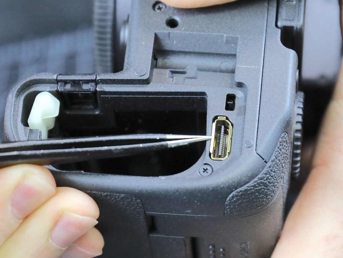
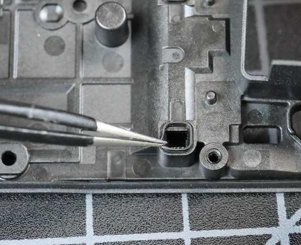
The camera looks pretty much like the other Canon cameras with the battery door off. That’s the connector for the WFT-R10 wireless transmitter, which is cool: It functions as a 2-battery grip plus provides ethernet as well as wireless connectivity, connecting up to 10 cameras to a server. This is not something I’m interested in myself; the onboard wireless is all I ever need. It seems a cool, albeit expensive, option for high-powered professional-type people.
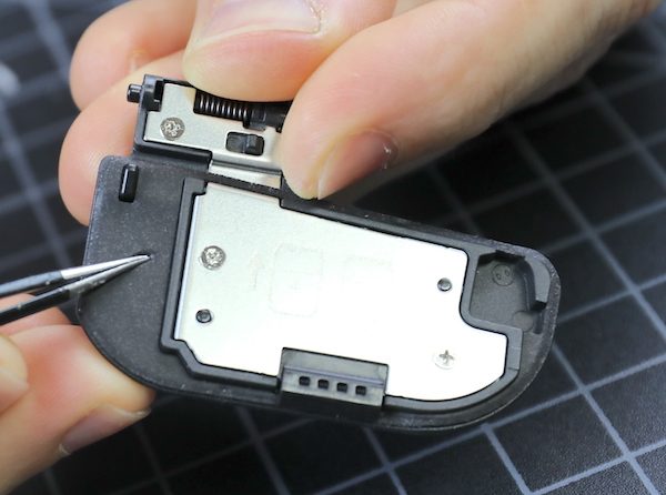
The battery door itself gives us our first pleasant surprise. In every camera, the battery door is a weak area for leakage. There’s usually some weather-resistant gaskets around the edge, which the Canon R5 has. In addition, the entire flat surface is soft gasket material in addition to the raised gaskets around the edges and hinge area.
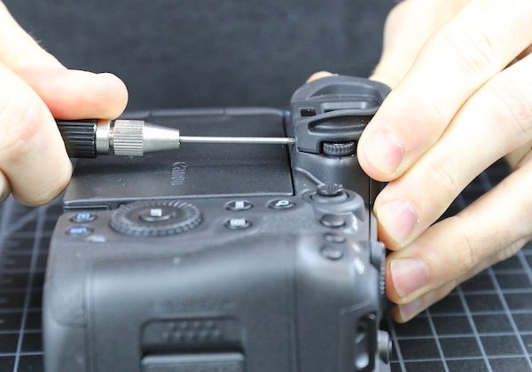
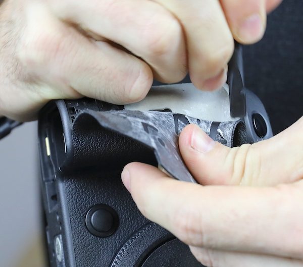
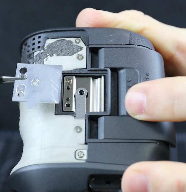
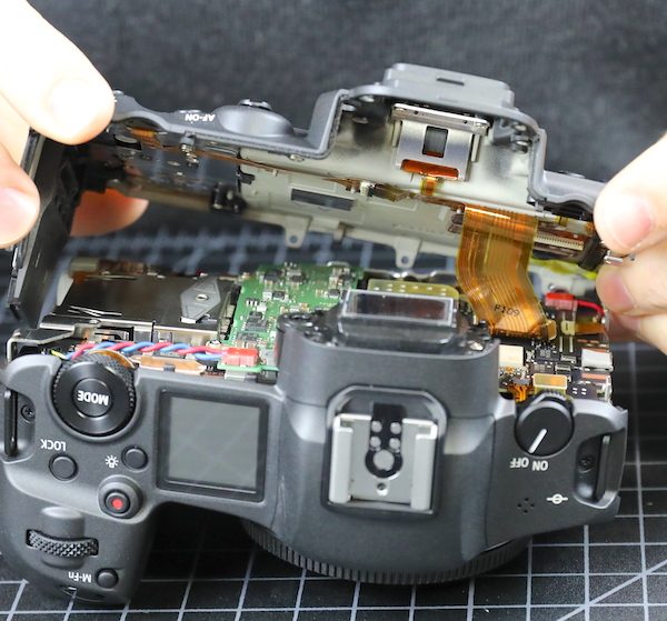
The viewfinder rubber comes off next, Canon attaches theirs with a couple of screws rather than a clamp.
Next, of course, comes The Removal of the Grips.
The key to taking off the grips, for those of you doing your own disassembly at home, is to keep as much of the double-sided tape on the grip as you can, which makes it easier to reapply. The grip material surface feels slightly different than earlier models to the touch, but it’s about the same thickness and flexibility.
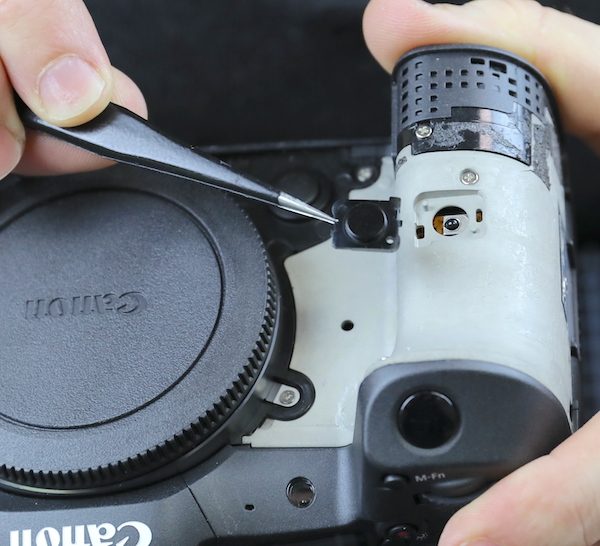
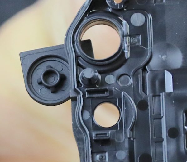
The cover to the remote control sensor is basically held on by the grip.
And there’s a metal plate covering the area of the card door hinge.
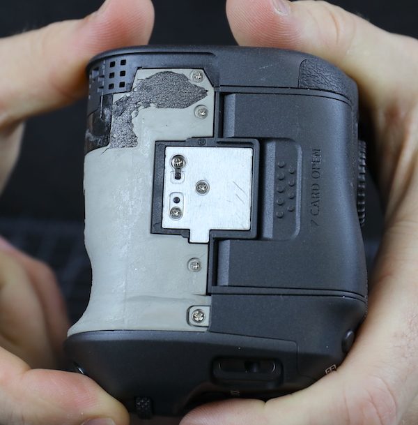
It seems to provide some reinforcing strength, but mostly a smooth surface for the grip rubber to stick to.
Now we have access to most of the screws and can start body disassembly.
The bottom plate comes off next.
The inside of the bottom plates shows us a new thing! We’re used to seeing a bead of rubber felt between the plastic pieces of the body to seal for the weather. Canon now has a soft rubber gasket along the mating edge of the pieces. This is much larger and provides a greater seal area than what we usually see. It seems to be attached to the body (in the old days, I would have said ‘vulcanized’) rather than being glued on.
The same material is used around the openings where the plate seals around other parts. Here they’ve completed the seal for the battery door hinge from the inside.
The metal tripod plate is sturdy and the actual tripod mount replaceable; both of these are things we consider important.
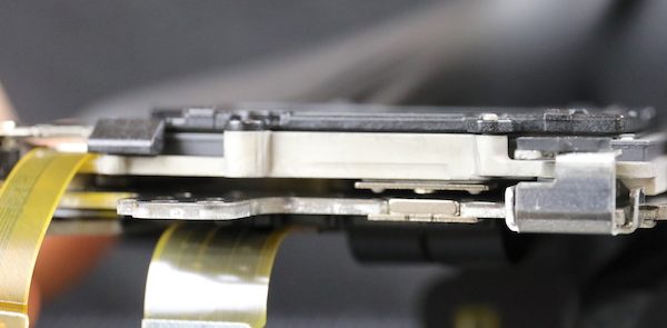
The I/O side comes off next, and again we see that big rubber lip sealing the entire piece. Also, note that both the HDMI and digital out ports are part of the main PCB, so secure your cables; tugging these ports loose will be an expensive main PCB replacement.
Another close up of the sealing gaskets from the side door. When we took these pieces apart, you feel the suction when they disengage. That’s not something we’ve seen in other cameras. The thing about weather sealing is it only takes one weak place to leak, but this sealing seems to be a step up from anything we’ve seen before.
While there are gaskets around the I/O ports, with any port unless the covers are closed, you lose weather-resistant integrity.
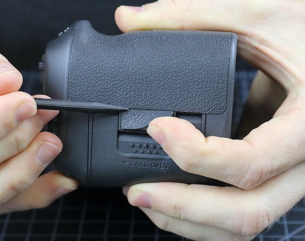
Under the card door, there is a thick foam similar to that on the battery door.
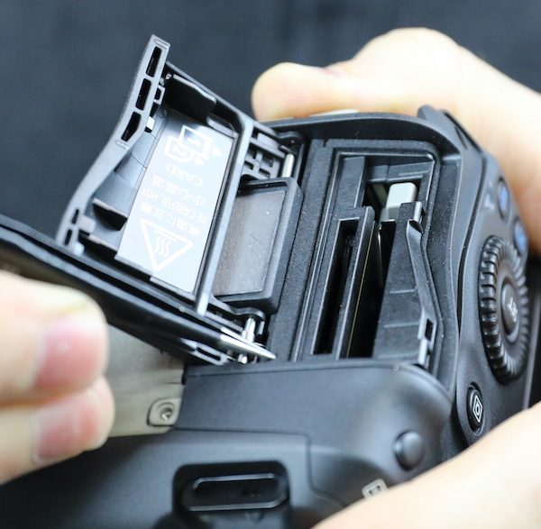
And there’s that big rubber gasket where the door plates fit with the rest of the camera.
OK, enough with weather sealing. You know weather sealing is outside my circle of trust, but I might put this within the rhomboid of reduced suspicion. I write off too many cameras from water damage every year to really trust weather sealing. This is good, but weather sealing isn’t about where it is good; it’s about where it can leak.
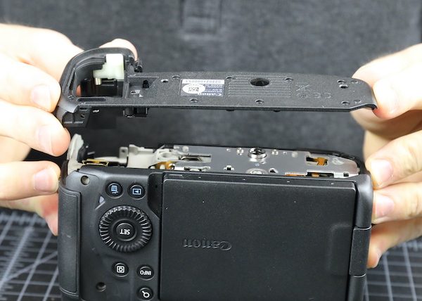
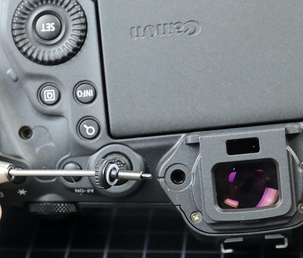
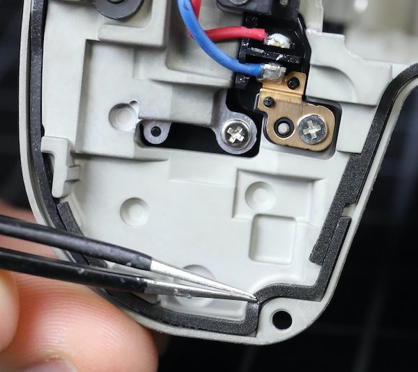
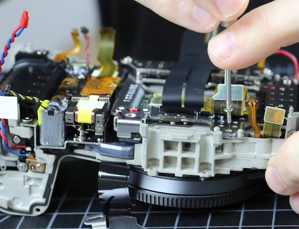
The next step is to take out the diopter adjustment screw.
And then the back assembly comes right off.
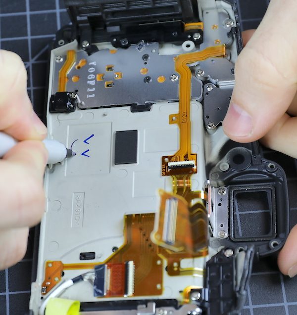
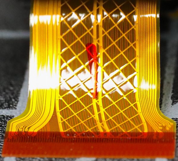
The back has more dials than the original R, but the LCD wiring appears identical; nothing much to see here. Except for the new, coppery colored flex they’re using on the LCD side, but not the switch side. I don’t know why the new flex material, but it is pretty.
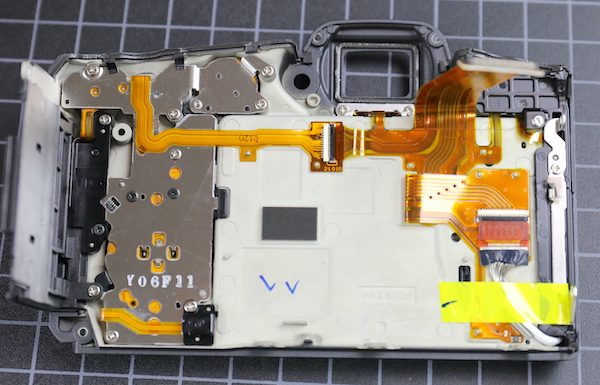
As you can see above, a Canon tech made his ink marks when this part passed inspection. Aaron decided to leave his mark of approval, too.
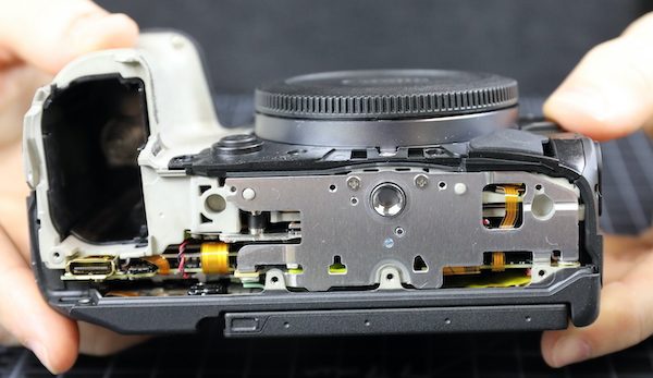
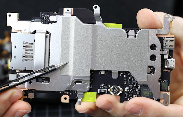
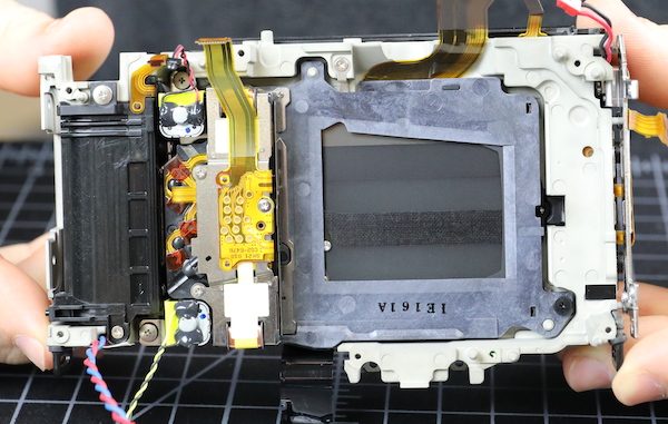
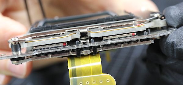
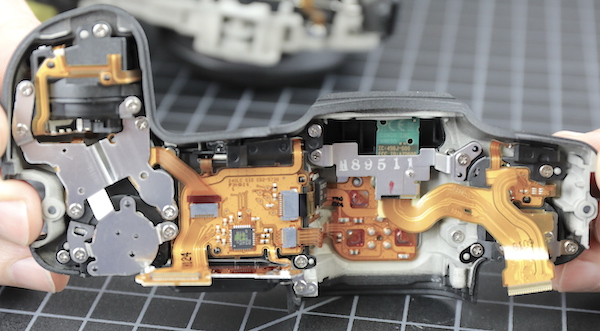
Now we can look into the camera and see the back of the circuit boards. This is immensely more intense and dense circuitry than we saw in the R. First of all, there’s a green sub-board that appears to be about DC power conversion. You can see some hefty wires entering it from the battery compartment. The larger, square chips are TPH8R903NL voltage converters. Over to the left on the black board, the large white chip is a Canon WiFi chip with what looks like an antenna plugging in just above it.
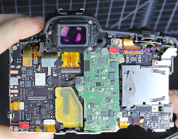
I am NOT an electronics expert, but I do know DC-DC conversion boards have to generate waste heat. How much depends on load, but I’m told 10%-20% of wattage isn’t unusual.
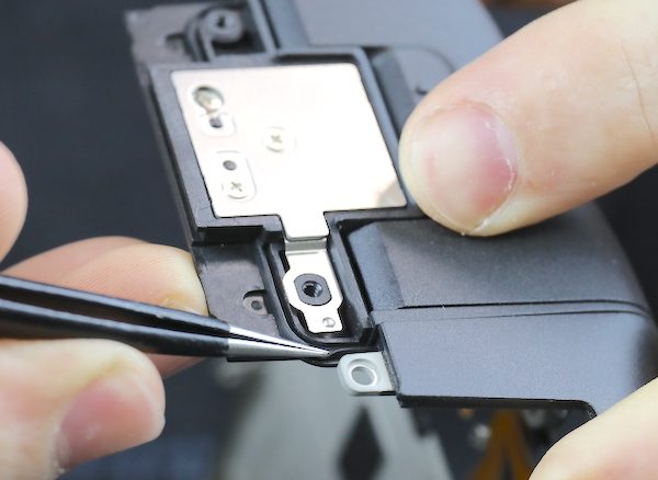
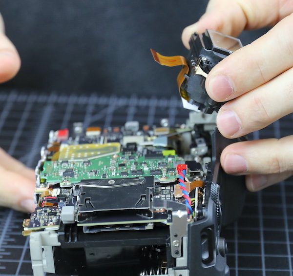
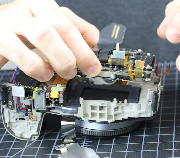
The viewfinder comes out next.
I’ll indulge in my flex fetish and show you a closeup of ‘the argyle flex’. We actually decorate our office with large printed macros of pretty flexes and circuit boards. Yes, I know I need some counseling.
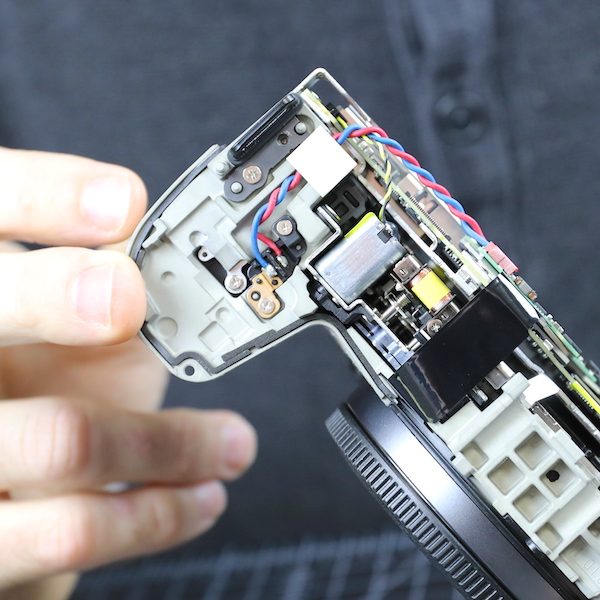
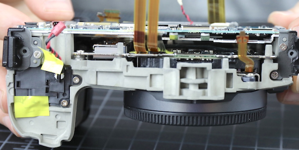
Anyway, with the viewfinder out, the top assembly comes off. Not much different, other than the number of buttons and dials, from the other R top assemblies. Except they’ve put all the connections between the top and motherboard in a single flex; usually, there are several. There is also, compared to the main part of the camera body, a bit of air up here.
The weather sealing is different around the top assembly compared to the rest of the camera. Where we had those hermetically rubber seals along the bottom and sides, we don’t see them on the top. On the top assembly, there is the traditional ‘top plate sticks out over the body plate’ thing.
With the standard foam sealing strips over some of the body plates. So we have the regular overhang and foam sealing on top that gives rain protection, but the bottom, the part you might set in a puddle, is tightly sealed. It makes sense unless we missed a leaking point on the bottom.
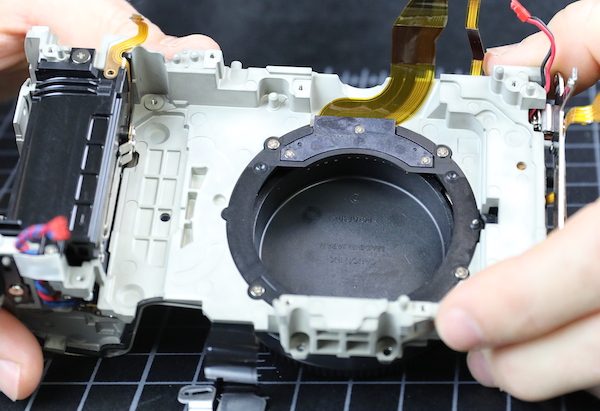
There’s not much sealing material over the lens mount area, though, so if there’s a weak point in weather sealing, I guess this would be it.
TOTAL SPECULATION: Maybe the looser sealing at the top, where heat rises, helps heat get out. The chassis is not a huge heat sink, and it’s wrapped in insulating rubber grip material. It radiates heat, of course, you can feel it, but that’s not an uber-efficient way to get rid of heat.
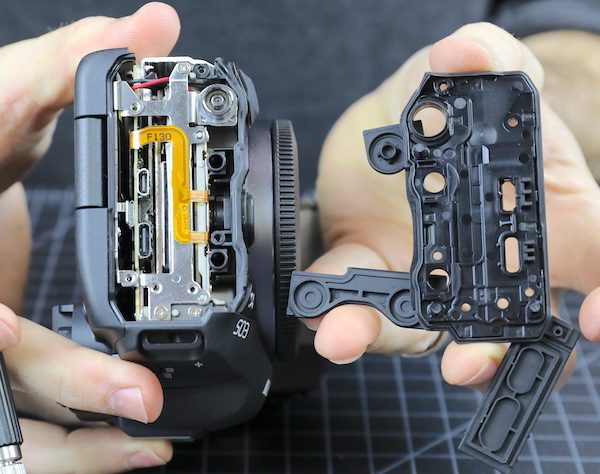
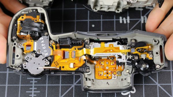
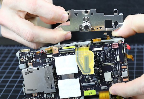
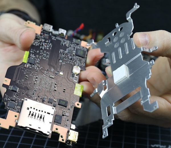
Now we turn our attention back to the main body. That accessory board comes off easily. It’s a single surface board; the backside is smooth.
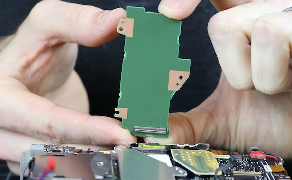
And a single view for those who do chip quests.
There’s an aluminum heat sink or electronic shield beneath that board.
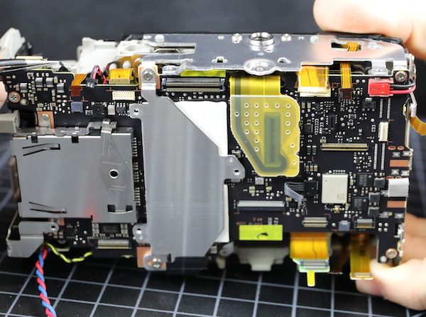
Electronic shields tend to be quite thin, but this is a manly piece of aluminum, 0.98mm thick. I speculate it’s more about heat than electronics. Notice I said ‘speculate’.
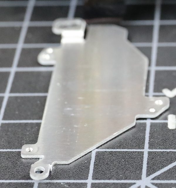
The aluminum shield connects to copper tracings at the top and bottom (and the bottom tracing connects to the metal base plate), plus it sits above the two thermal pads, so I’m feeling pretty comfortable that this transfers some heat.
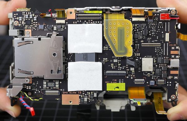
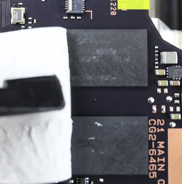
Peeling back the heat transfer pad shows the four SKHynix SDRAM chips we’ve already been told are there surrounding the main CPU.
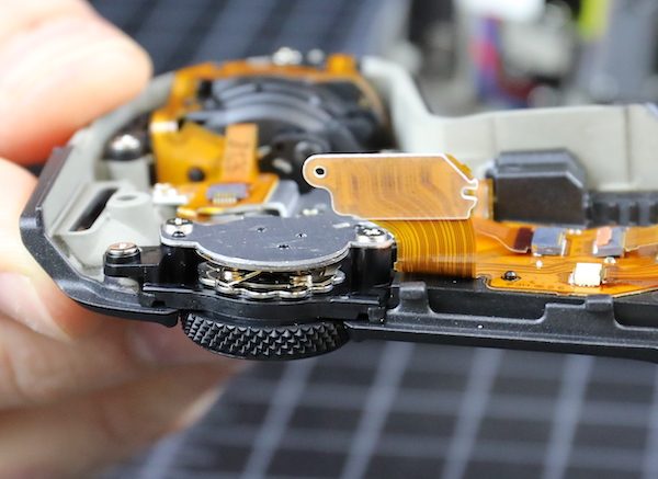
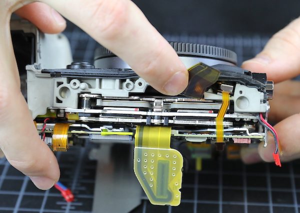
We took off the tripod plate next (note, we had to take off that top heat sink before the tripod plate, so they are indeed connected). Notice the tripod socket is screwed, not soldered, to the plate, so it’s easy to replace.
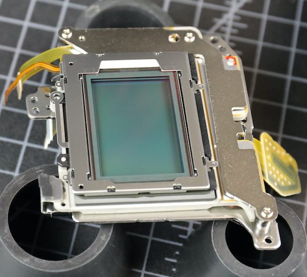
Now we can get a glimpse of the stabilizer/image sensor arrangement. There’s not much air down in there, particularly if you compare it to the original R.
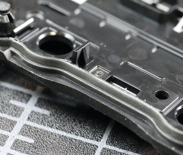
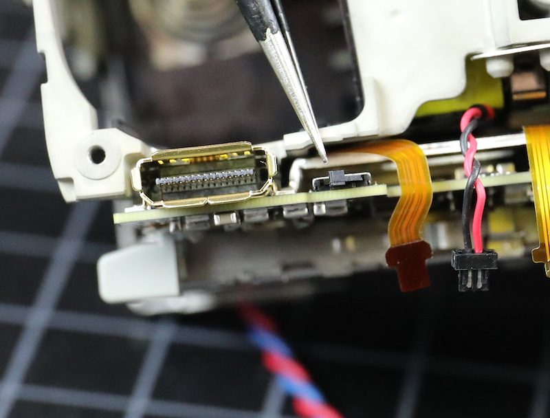
As long as we’re looking around the edges, I should show you the battery door switch, since people have been having a grand old time stuffing things in there to make the camera think its door is staying shut. This is a small, frail switch soldered directly to the motherboard and only held on by the solder. I have it on very good authority (my own) that it’s easy to dislodge the switch from the circuit board with just a little bit of torque, requiring a complete mainboard replacement, which is very pricey.
Having completed our camera body tour, we took out the main PCB.
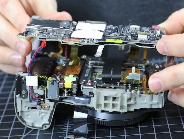
There’s another big aluminum heat sink on the underside. This one has a layer of electronic insulating tape over the sensor.
Removing this shows another thermal pad underneath the CPU. So it seems Canon is sending the heat from the SDRAM chips to one sink, and from the CPU to another. To some degree. (Get it? Degree?)
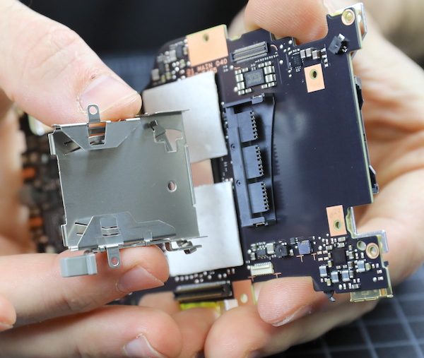
Both card slots are part of the main PCB, but we can remove the ejection mechanism for the CFExpress card, getting a look inside. Here you go; a picture of the inside. You can see why we think CFExpress is a lot sturdier than the long, bendable pins of old CF card slots.
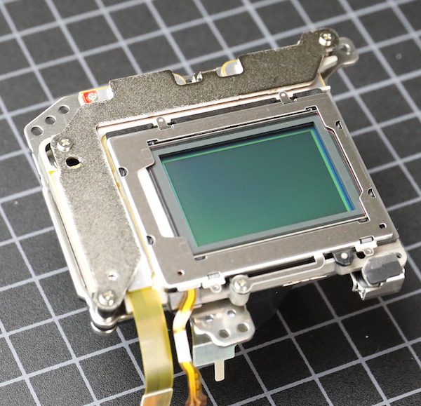
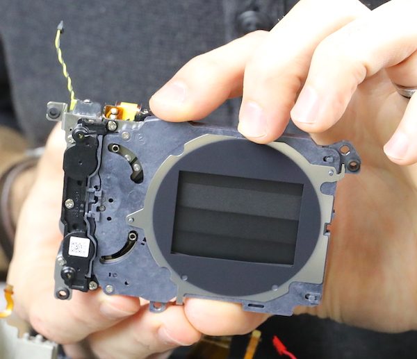
Going back to the camera, we get to see the back of the sensor / IBIS assembly and the huge flexes leaving there, as well as the shutter mechanism between the sensor and the battery compartment.
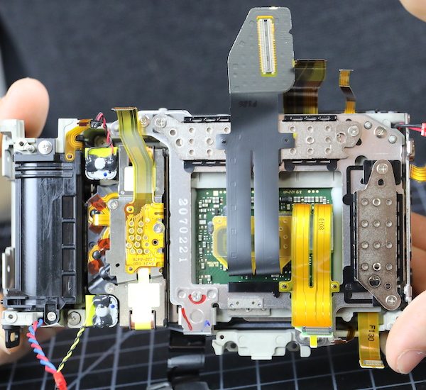
The sensor assembly is held in by three screws. As you can probably see, Canon has changed to shimming the sensor for flatness (in the R they used spring tension screws). Spring tension screws can theoretically be more accurate (depending on how accurately they measure), but I assume the vibration of an IBIS unit could loosen them over time; every IBIS camera we’ve opened uses shims.
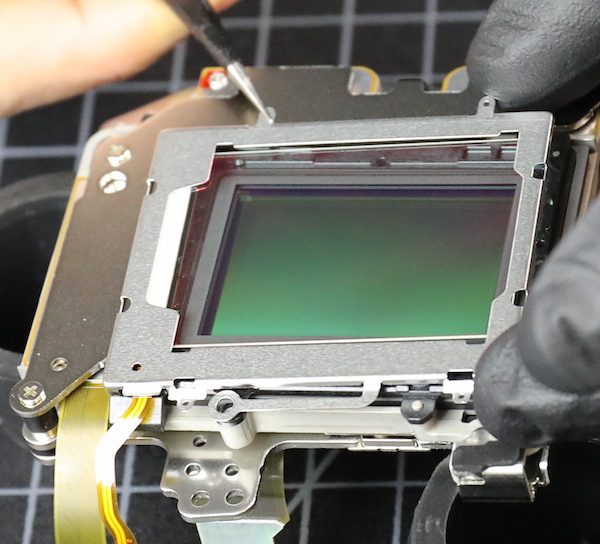
The sensor / IBIS unit comes out as a single piece.
The shimming for this one was 0.45mm, 0.45mm, and 0.24mm, so a pretty significant tilt compensation was made. And no, that’s not unusual for any camera.
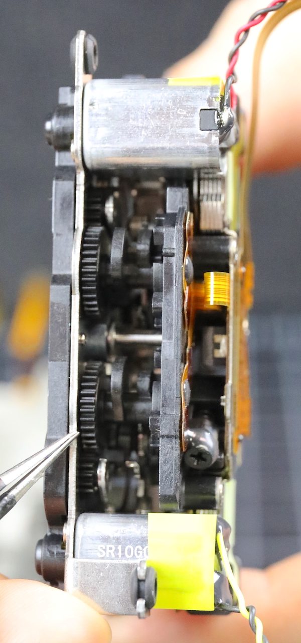
The only thing really left in the chassis is the shutter assembly, which is held in place by screws and posts.
These we don’t take apart, but then neither does the service center these days. Nobody’s got time to line up all the gearing, plus if you mess with it, you have to have factory software to recalibrate the timing.
With the shutter out, the chassis really has nothing left inside but the lens mount, battery case, and a few connection traces. You know something I’ve found interesting in all the jumping-to-conclusions about heat inside the Canon R5? Not one person has tested the heat conductivity of the chassis. (Spoiler alert: it doesn’t conduct heat well.)
Outside of the chassis sits our sensor and IBIS unit, which I’m quite interested in.
We aren’t going to get majorly aggressive here, but we’ll take off the cover plate.
Which comes off easily along with the outer self-cleaning glass plate.
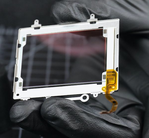
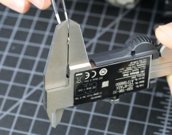
We can’t get an exact glass measurement without taking the sensor apart, and we have a bad habit of breaking glass when we do that, so it will have to wait for the first Canon R5 to die for a more accurate measurement. We estimated the total (including the front piece) at about 2mm, which is Canon standard.
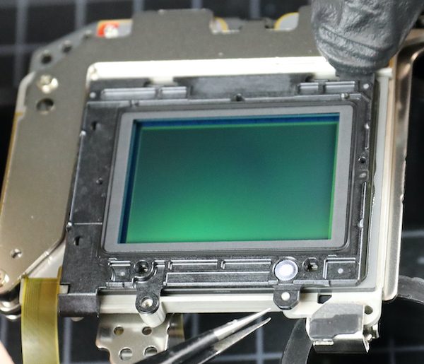
I also wanted to look at how the sensor is supported in the IBIS unit. We’ve found some fractures in cameras where the sensor is supported by several screws-through-plastic-tabs. There is one screw tab you can see above, but that was mostly for the cover plate.
On all the edges of the Canon unit, the sensor is mounted directly to IBIS plate; no tabs. That doesn’t mean it can’t break, of course, or glue come loose. But this seems sturdier to me.
On the IBIS itself, we can see the permanent magnets; the electromagnets are shielded here, so not completely obvious.
So What Did We Learn Today?
Not much that was surprising. What with the IBIS unit and a more intense chipset, the camera is pretty thoroughly filled up, there are lots of parts and not much air. There’s a new weather sealing method in the lower 2/3 of the camera that seems to give a really, really tight seal. And there we some pretty new flexes which matters not a tiny bit to anyone but me.
The IBIS unit is very compact but well-engineered. There are no tab connections that might be weak points; the sensor is connected to a flat plate around all its edges. That doesn’t mean there can’t be problems, of course, this is a new build, so we won’t know for a year or so.
There seem to be two separate heat sinks, one under the voltage board, another between the main PCB and the sensor assembly, with thermal pads to direct heat to each. At least one of them connects to the tripod plate, which might provide a secondary sink. This is a lot of heat sink compared to most photo cameras, but not even a fraction of what we see in a video camera. What I can’t tell from this is how that heat then gets out of the camera. It’s sure not air circulation.
Given how tightly sealed things are, I’m curious as to where the heat goes to get out of the camera; some further investigation is required there. A lot of people are talking about how the heat should move around inside the camera, slapping some thermal paste around, and doing things to manipulate the heat cut offs.
I’m a simple person. All I can think of is, ‘how does the heat get out of the camera?’ Sure it goes into the metal sinks, but once they heat up, then where? In a small photo camera, there’s not a lot of ventilation/convection current to get let the heat out. This camera is better sealed than most; I doubt there’s very much ventilation at all.
Somebody should look into that.
Roger Cicala and Aaron Closz
Lensrentals.com
September, the ninth year of 2020

142 Comments
Caleb Barrett ·
Neat. How common is the self-cleaning glass over the sensor, and how does that work?
Roger Cicala ·
Pretty common these days. I’m not an electronics person, but I believe it has both a piezo vibrator and generates a negative electrostatic charge. Put another way, how it works is ‘somewhat’.
Caleb Barrett ·
Hah, sounds about as effective as I expected, then. I was excited that maybe this was some exotic new thing. Thanks, Roger.
Timothy Smith ·
If someone didn’t need weather sealing, is there any logical place to put a couple of small vents. Is there room behind the LCD screen for some tiny holes
Roger Cicala ·
I’m looking at hot spots, but I would say the back under the LCD could be dremeled out and maybe the front hear the RF logo. Also you could take the plastic bottom plate off and cut it so only the part around the battery door goes back on.
Timothy Smith ·
Thanks for the teardown. I think the Tilda fan may turn the R5 to be a more predicable camera for video. We just have wait for someone to launch a line of R5 shells or if anyone is game enough to do some permanent modifications.
Jam005 ·
The Tilda fan/cooler still hasn’t been released as they had mentioned late July, However, It is merely a modified cellphone peltier radiator cooler. If you google search, you’ll find a gazillian cell phone peltier radiator coolers. The best being Memo and Blackshark FunCooler Pro etc. However, the camera body doesn’t seem to transfer much heat. Obviously for safety reasons.
Robert M ·
Most cellphone coolers will not fit in a camera. I did find a smartphone/tablet cooler that might fit. I am sure the Tilta one will probably be overpriced, but at least it will be a bespoke version for the R5. The R5 is pretty easy to keep cool inside and outside temperatures are dropping. As long as the Tilta cooler is available before the summer than everything should be fine except for those in the southern hemisphere.
Roger Cicala ·
I don’t know many things, but this I do know. There is absolutely no way putting that fan on the back of the R5 is going to make a difference. They may release it, they may sell it, people may buy it. But it’s not gonna work.
UNLESS they plan on cutting off the back of the camera in that area and even then I have many serious doubts it has much effect.
RNG ·
The benefit of that would be so small that it is not worth of it. Realistically the exchanged amount of air over the heat shink area there would probably give few % more of use time, until the heat shink’s capacity of spreading the IC hot spot gets saturated again.
Maybe the camera could be put on a puddle of ice water, as they made the weather sealing at the bottom near IP65 and above grade :).
Roger Cicala ·
@RNG I’ve got little knowledge of thermal transfer beyond the college Physics I mostly forgot, so serious question: would thermal connective tape or some soldered metal traces linked to the existing heat sinks and brought out of the camera to a larger, radiated sink be of significant benefit? Or would that probably not provide enough heat flow?
obican ·
If you want to go down some rabbit hole, you can look up thermal conductivity of thermal pads, thermal paste and heat pipes. I’m not an engineer either but speaking from experience (about 20 years of PC cooling at a hobby level), you’d want something more than simple interconnected pieces of metal to transfer heat effectively over that distance. Heatpipes would’ve been a great solution but how would you make that work within a camera?
Maybe internal heatpipes from the CPU/RAM/Other hotspots to a large bottom panel made of copper or aluminium and an external battery-grip-like-cooler that wlil have a large surface contact with that piece of metal and fans to cool that battery grip?
RNG ·
Indeed. But nevertheless, more mass, more heat capacity the object will have. So making something physically bigger will help. Even better if in the process one can increase the surface area to the outside, so the piece can more easily to release the heat.
But on the other hand, the bigger the thermal capacity, the longer it will get it cool again, once the limit of thermal capacity is reached.
I guess this might actually be one of the R5 problems. There’s way bigger mass in the cooling elements than usual, so it will consequently also take longer to get them enough cool again, once the limit was reached.
GNGGGG ·
Indeed. But nevertheless, more mass, more heat capacity the object will have. So making something physically bigger will help. Even better if in the process one can increase the surface area to the outside, so the piece can more easily to release the heat.
But on the other hand, the bigger the thermal capacity, the longer it will get it cool again, once the limit of thermal capacity is reached.
I guess this might actually be one of the R5 problems. There's way bigger mass in the cooling elements than usual, so it will consequently also take longer to get them enough cool again, once the limit was reached.
RNG ·
It would definitely help. Obviously the more material to transfer the heat, the more effective it would be. Even better if something like heat pipes could be used that will internally transfer the heat via gas-liquid exchange, which will be one of the most effective ways to transfer heat, as the liquid boiling to vapor binds a lot of heat quickly.
Roger Cicala ·
Yeah, I’m not sure about the diameter of heat pipes. You could certainly do something on the order of running, say, 16 gauge copper wire between those plates, but not anything much larger than that.
Olandese Volante ·
Thermal conductivity is very much analogous to electrical conductivity, so the thicker (more cross section) and shorter your conductor, the lower the (thermal) resistance and the lower the temperature difference (analogous to voltage) across it at a given heat flow (analogous to current). In fact one can make simple thermal models in circuit simulators using resistors and capacitors, the latter to simulate heat capacity. Hook up a current source as your heat source and Bob’s your uncle.
That said, my guess is that hooking up any type of external heat sink would require a considerable cross section of copper in order to be of any benefit. Plus the existing heat sink being aluminum, which isn’t easily solderable. One might replace the existing sink with a copper one and extend it out through the bottom of the camera.
Heat pipes can transport prodigious amounts of heat in moderate cross sections but the preferred orientation is with the hot end below the cold end. They will work reasonably well with both ends level because they use capillary action to return the working fluid to the hot end, but they lose efficiency quickly if the capillary action has gravity working against it. So if you’d want to stick a heat sink to the bottom of the camera you’d have to operate the camera upside down for the heat pipe to work.
Roger Cicala ·
Thank you, that makes perfect sense. I learned something today!! That’s why I do this blog, because I learn stuff!
Roger
Olandese Volante ·
I much appreciate your teardown articles and commentary, for exactly the same reason.
I see engineering as the Art (yes, capital “A”) of practical application of Science, and the true artist learns whenever, wherever there’s something worthwhile to be learned.
obican ·
Good call regarding the direction of heatpipes.
GNGGGG ·
The benefit of that would be so small that it is not worth of it. Realistically the exchanged amount of air over the heat shink area there would probably give few % more of use time, until the heat shink's capacity of spreading the IC hot spot gets saturated again.
Maybe the camera could be put on a puddle of ice water, as they made the weather sealing at the bottom near IP65 and above grade :).
Zak McKracken ·
Some small air holes won’t help because at these scales, thermal convection will be close to zero, especially if there’s no place where cool air can get in if the warm air exits at the top…
You’d have to make to openings on different sides of the heat source, then force air through, lots of it.
GulliNL ·
There are lots of people that mod their (older) DSLRs with active cooling fans for Astrophotography. Since you need long exposure times, and higher temperatures introduce more noise in the image. So what most people do is flip out the screen permanently, and cut out the plastic backing from where the screen would sit. Then fit a small CPU fan to the back of the camera.
MJD ·
Yes, like this:
https://uploads.disquscdn.com/images/13dd907691ffc9d5b8bd6b9afa60cc149abc221bb9357adae3e89842bdc93c0f.jpg
Andreas Werle ·
Hi Aaron and Roger!
Thanks for the pretty teardown. 3 weeks ago Zach said, that you will perhaps disassemble a R5, when one body came back damaged. So was this R5 broken and could you manage to repair it?
Greetings Andreas
Roger Cicala ·
We haven’t had a damaged one, we actually got this one back from a local renter early in the morning and did this immediately. It went back out that afternoon, we’ve only received like 20% of what we’d ordered at this point.
Nathan ·
The tripod mount is attached to the heat sink. So you could pretty easily engineer a small heat sink that screws into the tripod socket, yeah?
Mel Gross ·
Interesting idea. The question is what percentage of that heat gets to the socket. It might be just a small amount. Still, it might help somewhat. You never know until you try it. When I get mine, if I remember, I’ll make something up in my shop.
Scott ·
I can’t remember now where I saw it, but someone else did a teardown and found what he thought was a timer circuit which would imply that the lock up is timer determined and not heat. Therefore, figuring out how to dissipate heat better may not help.
Jam005 ·
They were quite wrong
Athanasius Kirchner ·
There are conflicting reports. Apparently, heat does play a role in the R5’s decision to shut off… as does the cripple
hammertimer. So, it’s complicated.DR ·
This report, along with the new firmware, disproves the whole “cripple timer” conspiracy. But I’m sure people will hold on to that for as long as they hold on to the Bill Gates/Flat Earth theories.
Athanasius Kirchner ·
I’d say it’s quite the opposite, the FW update did very little but lessen the severity of the cripple timer. The change in temperature is small, but the reduction in rest periods can be dramatic.
RNG ·
The timers in these sort of cameras will be in the CPU, so no.
The CPU will have internal heat sensor (and maybe couple more around, if there’s other heat sensitive components), and once it detects too hot temperature, it will shutdown itself. Simple as that.
David ·
Canon told one of the reviewers of the latest firmware update that there are 3 different temperature sensors in the body. The reports of temperature in the EXIF will only record one of these. The CFe card/reader also is a source of heat. Not sure how to fix that except external recording with no cards in or having the CFe bus turned off until needed – but that will have a small time delay to start up again
Scott ·
It seems that it is more complicated than just a simple temperature sensor. People have tried various methods to cool the camera and they don’t influence the cool down period, so there must be some kind of timer function involved as well. Plus I’ve read about other hacks that seem to decrease the cool down period. Personally, I think Canon is taking too much flak for this “issue.” They were upfront about the limitations and given the amount of data being moved, it’s not surprising at all that heat would be an issue.
RNG ·
The IC temperature will be totally different than what you measure from outside.
The thermal limits of IC won’t be linear either, so it will allow you to reach temps like 95 degrees internally, until it shutdowns, but then you need to reach steady 70 degrees internally to again continue. Once you get the heat shinks up to the temps that the 95 degrees is reached, you’ll have to wait quite some time that the IC can again operate for longer periods.
Also, the IC temps will have different ramp up angle than the body temp, so IC shoots up fast in heat, the cold heat shink will cool it down until it gets saturated with heat, and hence you will need to get that heat shink cold again in order to continue. Once you turn the IC on again, it will immediately start heating it up again at that high heat rate. It is like heating a big piece of iron with a blow torch. Held the other end of the iron with your hand, and start to heat it up from the other end. Once your fingers start to burn, stop, and see how long it takes until you can again start heating it up for longer periods without your fingers burning.
Scott ·
I understand your point, however, employing an active cooling method on the outside of the camera should reduce the internal temperatures faster than not, shouldn’t it? I realize that we are talking about chips buried in the middle of a poorly conducting body, but it seems to me that actively cooling the exterior will allow the insides to dissipate heat quicker. The cooled exterior will create a stronger gradient than doing nothing so I would expect some shortening of the shut down period, even if only by a few minutes.
RNG ·
Yes it is so, but for fast cooling, you would need to get the internals cool fast. There’s quite a lot of barriers here to reach the point where cooling placed on the outer shell will actually start cooling the internals quicker. It is not helping that the internal air will actually act like a heat insulation, as air is a bit reluctant to release its temperature (copper has thermal conductivity of 384, air has 0.026).
So to effectively cool it fast, you would need to get your hands directly on the heat sink and apply the cooling on that. Otherwise it will take some time to dissipate it via the outer body shell, even if trying to speed it up with cold backs etc.
Scott ·
I agree. Its like a styrofoam cooler in my mind. The contents stay at a given temperature for a long time whether or not the cooler is sitting in the sun. However, I would expect some difference, and maybe there is, just not enough to make a marked change in cool down times. Either way, it’s a pretty remarkable camera. I gave up on Canon a few years ago, but they’ve certainly created a compelling camera.
GNGGGG ·
Yes it is so, but for fast cooling, you would need to get the internals cool fast. There's quite a lot of barriers here to reach the point where cooling placed on the outer shell will actually start cooling the internals quicker. It is not helping that the internal air will actually act like a heat insulation, as air is a bit reluctant to release its temperature (copper has thermal conductivity of 384, air has 0.026).
So to effectively cool it fast, you would need to get your hands directly on the heat sink and apply the cooling on that. Otherwise it will take some time to dissipate it via the outer body shell, even if trying to speed it up with cold backs etc.
GNGGGG ·
The IC temperature will be totally different than what you measure from outside.
The thermal limits of IC won't be linear either, so it will allow you to reach temps like 95 degrees internally, until it shutdowns, but then you need to reach steady 70 degrees internally to again continue. Once you get the heat shinks up to the temps that the 95 degrees is reached, you'll have to wait quite some time that the IC can again operate for longer periods.
Also, the IC temps will have different ramp up angle than the body temp, so IC shoots up fast in heat, the cold heat shink will cool it down until it gets saturated with heat, and hence you will need to get that heat shink cold again in order to continue. Once you turn the IC on again, it will immediately start heating it up again at that high heat rate. It is like heating a big piece of iron with a blow torch. Held the other end of the iron with your hand, and start to heat it up from the other end. Once your fingers start to burn, stop, and see how long it takes until you can again start heating it up for longer periods without your fingers burning.
DR ·
All this is moot now with firmware 1.1.1 as the camera responds very well to cooling. In fact, some people here in Canada are getting basically unlimited recording in 4k 60 with fall temps (10c or so). Others have also been getting near unlimited record times using usb fans. This disproves the whole “hard timer cripple” nonsense.
Scott ·
It doesn’t disprove anything of the sort. It just means that Canon expanded the limits they built into the camera to give better performance. Hopefully, that doesn’t mean greater risk of damage from heat.
Olandese Volante ·
Someone found the RTC* chip (in the R6) and called it the “Overheat Timer Chip”. I almost fell over laughing.
* for those not familiar with the jargon, RTC stands for “Real Time Clock”. It’s the thingy that makes it possible for the camera to put the exact date and time when a picture was taken in the picture’s EXIF data. Every digital camera has one. It’s always running even when the camera is off or the battery is out because it’s powered by its own little coin cell.
GNGGGG ·
The timers in these sort of cameras will be in the CPU, so no.
The CPU will have internal heat sensor (and maybe couple more around, if there's other heat sensitive components), and once it detects too hot temperature, it will shutdown itself. Simple as that.
Roger Cicala ·
Stay tuned, same channel, same week. Spoiler alert: no clear answers, but more information. https://uploads.disquscdn.com/images/f3c65a1f2c19ec2c30dfe673340e8003797bd4d9b4e8ec7b7caf7f8dab3eca60.jpg
Athanasius Kirchner ·
Roger, this is kinda OT – did you manage to reassemble the 600mm DO correctly? And if you/Aaron did, how do you like it?
Roger Cicala ·
We did; the barrel extended switch was supposed to go in pointing one way, we pointed it the other. It was . . . . fine. Decent images, not great but decent. Easy to carry around, AF was pretty accurate which I was worried about.
Rashad ·
OT is NG but MBT
Matt Saunders ·
The CPU / image processing chip, the RAM chips, the CFe card etc. of course contribute to a camera’s heat output. Unfortunately, their actual temperatures are quite difficult to measure from the camera’s outside.
There is, however, one important component whose temperature can be fairly easily measured from the outside: the image sensor.
Image sensors can also be non-negligible source of heat. Furthermore, if the image sensor heats up, thermal noise in the pixels increases, degrading image quality.
An interesting experiment would be to take a picture of the Canon R5’s image sensor through the bayonet mount with your infrared camera.
The bayonet mount should be covered with Saran wrap to emulate the fact that, in normal camera operation, the mounted lens and the lens bayonet’s weather sealing prevent cooling outside air from circulating in the image sensor’s vicinity. Of course, take test pictures with the IR camera beforehand to ensure the particular type of plastic cling film used is transparent to IR and thus doesn’t affect temperature measurements.
Once it’s ascertained that a layer of plastic film doesn’t influence the IR camera’s readings, here are some measurements that could be taken:
1) before powering up the Canon R5 — this establishes a baseline for the temperature increases, and is also a sanity check: the temperature reading from the image sensor should, obviously, be identical to the room’s temperature
2) 10 minutes after power on, the Canon R5 prevented from sleeping but otherwise left idle (camera CPU is executing code, image sensor is active, feeding signal to the EVF). To keep “idle mode” comparisons between various camera models fair, a human should stare into the EVF for the whole 10 minutes, as some cameras might lower the EVF refresh rate, image sensor scan rate and thus lower their power consumption if they detect no human eyeball behind the EVF.
Give camera a few hours to fully cool down to room temperature, and then:
3) power it on, immediately start filming 4K video in best quality for 10 minutes, and take temperature measurement.
This could show differences in heat output (that is, energy efficiency) between various camera manufacturer’s image sensors, as well as the possible influence of maximising the contact area between the image sensor’s ceramic package and the magnesium IBIS frame, as said frame might have a bit of a heat sink effect.
Yugo Nakai ·
Sure – 1/4″ 20 screws are pretty standard, add a copper plate with a matching hole to screw through, and see how warm it gets (or how cooled down the camera gets during video). If that copper plate happens to be sitting on a gel ice pack, that should get you a nice dT, right?
Scott ·
I’m curious about reassembly of the rubber sheets from the outside of the camera. My experience with peeling off the rubber is that it never adheres as well and I usually end up with a corner lifting. Do you treat it with anything before sticking it back on?
Roger Cicala ·
We tend to use a heat gun both coming off and going on. Occasionally we mess up the tape in a place, but you can buy sheets of double sided tape and cut out the shape you need to finish it.
Trey Mortensen ·
After the IBIS checks you did earlier, I’ve been curious about the durability of the systems. Before I bought an a7iii, I was actually really worried about that (I don’t have a great track record with my camera bodies and drops…). I’ll love to hear about how the durability of this Canon unit is after a few years in service!
David Beall ·
Great tear down! Always amazing to see inside the new cameras. So how does this weather sealing compare to the 1Dx3/ 1Dx2? I’ve always been curious because I’ve never seen a 1 series body opened up to show the weather sealing. Also, is the yellow/green-ish body material plastic or coated magnesium? Can’t make out what it is. Thanks!
Roger Cicala ·
These rubber gaskets are a different type we haven’t seen before, although we have not torn down a 1DxIII so it might have them too.
Jeff Sellenrick ·
Great tear down. Can you explain what we are looking at with the chassis? The white frame looks like polymer, but I’m guessing that’s the magnesium alloy with paint on it?
Also, same question about the R. Your teardown shows a lot of what I thought was plastic, which didn’t match Canon’s graphic of the shiny metal frame. Thanks
Athanasius Kirchner ·
The type of mag alloy used in many camera bodies is white… well, the oxide layer that forms on top of it when exposed to oxygen is. The paint is actually the stuff that makes it look black on the outside.
Roger Cicala ·
I am not skilled in alloys and metallurgy, but it’s very light weight, has a rough texture where it’s not painted, nothing like the smooth surface of a metal sheet at all. It’s more rigid than most plastics / polycarbonates of similar thickness, but doesn’t seem to weigh any more.
Athanasius Kirchner ·
Yep, I know that feel. The OG Sony A7’s were made of the same material, which is also white on the inside. It’s presumably some form of zinc-aluminum-magnesium alloy, which is the most typical (and cheapest) of them.
Roger Cicala ·
It really is quite a unique texture. Almost like it was foamed on a very small scale, even though it wasn’t.
Zak McKracken ·
Based on what little I remember from materials lectures at uni: I know two ways to produce this kind of free-form metal shapes which could explain the surface texture:
1: casting, which is often done with some type of fine sticky sand
2: Sintering, i.e. taking a very fine powder and putting it under a lot of pressure.
Then again, it might also be made from a cruder piece of solid material (produced in whatever manner), and milled into shape, then anodized or painted...
Olandese Volante ·
Diecast metal usually does have quite a bit more surface roughness than rolled sheet, even when the die doesn’t have obvious tool marks from machining etc.
Olandese Volante ·
MgAl diecast alloy is dull whitish gray (machined bits are somewhat more shiny), but the inside of the shell doesn’t look like bare alloy. What we see here is probably a primer coat. Most MgAl diecast alloys do need a primer coat if you want to paint ’em because otherwise the paint is likely to come off very quickly.
Athanasius Kirchner ·
Ah, that makes total sense.
RNG ·
The weather sealing or weather resistance purpose is to stop capillary action – for this, just anything of “space filling” material is enough, like a 0.5mm piece of foam. Those rubber things at the bottom start to get closer to the IP65 classification that can also withstand some pressure.
Heat in these sort of products is by most transferred via conduction, not convection. The purpose of a heat shink is to just spread the heat from a tiny hot spot into larger area – basically to keep the tiny surface area IC internal temperature below 95 degrees or 120 degrees Celsius. Fanless convection is not much of a help, as there’s no room for more surface area for the cooling elements, what convection inevitably needs. The amount of air one could exchange within the enclosure is so small that it won’t probably affect much at all on the thermal load. Only option to improve cooling here is just to go bigger surface area, so bigger body.
Canon should have made this camera white, so it does not unnecessarily suck more heat out of sun light 🙂
Brandon Dube ·
Black objects also make good radiators. Double edged sword.
Roger Cicala ·
@ Brandon Dube Wish you were still here to help me decide where to cut the holes for the heat sinks. We were fearless back in the old days. 🙂
Actually came up the other day, Aaron and I were deciding about taking some risk of other, one of us adamantly said no, and the retort was “Well, if Brandon was here we’d have done it.”
Brandon Dube ·
It’s better to
ask forgivenesswait no that’s not it hmmpay a repair billhmm no not that either figure out how to fix it than ask permission 😉asad137 ·
Brandon, you should know that most white thermal control paints (such as those used in spacecraft thermal control) are ‘black’ in the thermal infrared, so they make good radiators for things that see sunlight.
Brandon Dube ·
Could you define what you think “thermal infrared” is? x to y microns will do.
Rashad ·
Asad137 is right
Brandon Dube ·
“thermal infrared” is not well defined. MWIR gives you strong thermal signatures, but is far away from the peak in the radiation of a relatively cool black body. You would need to have wavelengths in the range, say, 25-100 microns, to be at the peak. We made the Herschel space telescope for those wavelengths, which spurred development of a lot of novel measurement methods for things in that wavelength range. Those tools, and that data, is really not commodity at all.
So if asad means MWIR, I’d agree that a lot of white paints are pretty black in those wavelengths. If they meant white paint is good for emissivity of an object ~ 200F or lower, no – I would very much disagree.
asad137 ·
You would then very much be wrong. The Spacecraft Thermal Control Handbook (Volume I) has room temp emissivity values of ~0.8-0.9 at for common white spacecraft thermal control paints.
On page 142 of the STC, there’s an example curve for “white paint” (which I assume is some particular paint’s curve that is used as a “typical” curve) that has absorptance > 0.8 starting from 10µm (and longer), which, coincidentally, is right around the peak of the blackbody curve for a 300 K object (and, of course, there’s more energy emitted below the peak than above it).
But hey, you don’t have to take my word for it. Ask any of the thermal engineers in 382 or 353 (of which I used to be one) and they’ll tell you the same thing 😉
Brandon Dube ·
I was wrong, you are right. I overestimated how quickly the peak moves to the right as the body temperature is lowered.
asad137 ·
The peak of a 300 K blackbody is around 10µm, so somewhere around the 5-30 µm range for room temperature stuff is about right.
David ·
The only place for heat conduction outside of the body is via the tripod mount. I tend to keep my arca swiss plate on my R5 since I forgot to bring it one time for my tripod and I notice that it did warm up when I did some tests (didn’t we all when we got it!) for thermal overheating. As it is connected to one of the heat sinks (spreaders), I speculate that a Peltier circuit connected to the tripod mount could be a reasonable improvement of the video limits.
RNG ·
First the conduction happens from the ICs to the heat pads and from the there to the heat sinks. This is by far the most important part of the cooling, at will even out the hot spot of heat that forms inside the IC that the IC cannot tolerate.
The next task is for the heat sinks to transfer the heat to the surrounding panels. Either via direct conduction (screws and other physical connections), IR conduction, or air conduction.
Only place where convection here can help would be to exchange that hot conduction via air into colder air. That would be convection heat transfer. Now, the heat capacity of those big heat shinks is so much bigger than the air around them, that if you exchange that air passively, the amount of reduced heat exchange will be quite minimal in comparison to what those managed to radiate via conduction. Hence the final conduction surface to the open air will be the outer panels of the body.
I frankly do not believe this camera cooling can be any further improved internally, except by making it bigger. And obviously SW and HW updates in further iterations can reduce the thermal load overall.
Attaching a peltier element to the bottom might definitely help. Looking at the body and the heatshields, I’d say the best place to cool this down is the area behind the screen, though. The IR conduction of those heatshields will mostly hit the rear panel, and it also has most surface area against the hot air inside.
GNGGGG ·
First the conduction happens from the ICs to the heat pads and from the there to the heat sinks. This is by far the most important part of the cooling, at will even out the hot spot of heat that forms inside the IC that the IC cannot tolerate.
The next task is for the heat sinks to transfer the heat to the surrounding panels. Either via direct conduction (screws and other physical connections), IR conduction, or air conduction.
Only place where convection here can help would be to exchange that hot conduction via air into colder air. That would be convection heat transfer. Now, the heat capacity of those big heat shinks is so much bigger than the air around them, that if you exchange that air passively, the amount of reduced heat exchange will be quite minimal in comparison to what those managed to radiate via conduction. Hence the final conduction surface to the open air will be the outer panels of the body.
I frankly do not believe this camera cooling can be any further improved internally, except by making it bigger. And obviously SW and HW updates in further iterations can reduce the thermal load overall.
Attaching a peltier element to the bottom might definitely help. Looking at the body and the heatshields, I'd say the best place to cool this down is the area behind the screen, though. The IR conduction of those heatshields will mostly hit the rear panel, and it also has most surface area against the hot air inside.
GNGGGG ·
The weather sealing or weather resistance purpose is to stop capillary action - for this, just anything of "space filling" material is enough, like a 0.5mm piece of foam. Those rubber things at the bottom start to get closer to the IP65 classification that can also withstand some pressure.
Heat in these sort of products is by most transferred via conduction, not convection. The purpose of a heat shink is to just spread the heat from a tiny hot spot into larger area - basically to keep the tiny surface area IC internal temperature below 95 degrees or 120 degrees Celsius. Fanless convection is not much of a help, as there's no room for more surface area for the cooling elements, what convection inevitably needs. The amount of air one could exchange within the enclosure is so small that it won't probably affect much at all on the thermal load. Only option to improve cooling here is just to go bigger surface area, so bigger body.
Canon should have made this camera white, so it does not unnecessarily suck more heat out of sun light :)
Athanasius Kirchner ·
Did you just assume that Canon tech’s gender, Roger!? You’ll get canceled! /JK
Seriously though, lots of women work in Japanese assembly plants… I’d say there are more females than males, just from all those factory tour videos and articles that have become so popular now.
I get the feeling that Canon needed to put way more copper in the R5. At least made the heatsinks out of that material, and then put an aluminum grille on the back like Sigma did with the fp.
Roger Cicala ·
Oops. Yes I did and I shouldn’t have. Statistically I suspect you are correct, and I respectfully change to ‘she’.
Athanasius Kirchner ·
No worries. I think we should be thankful to all the women* working hard to build our gear 🙂
*and the men too.
Stefanie Daniella ·
Canon scrutineers should look more closely at vast differences in both energy requirements and image data processing heat generated from image sensor and (on-sensor and off-sensor) processors, image display, and memory recording storage:
?Old Canon RAW CR2 vs newer faster more modular energy efficient Canon RAW CR3+CRM (better mathematics = less waste heat output)
CR3/CRM Advantages (needs less energy; can process faster, sooner, more image data; thus generate less heat during image data handling):
?it started after EOS 1DXMkII (2016 Feb) … in summer (2016 June) new RAW Canon patent, just prior to emergence of CR3, albeit lowkey for EOS M50, then a bit more on EOS R, and slowly unveiled its (CR3+CRM) hidden full potential culminating in EOS 1DXMkIII + EOS R5 (+R6)
?this deliberate slow rollout of new Canon RAW CR3/CRM Advantages was necessary to keep competitors (and anti-canon consumers) off-balance and unlikely to ever match Canon for the next 2 decades in “Actual-Capture IMAGE DISPLAY LIVE” exclusive capabilities “Blackout-Free” (even with Mechanical Shutter High-Continuous (RAW) Stills fast-action sports Shooting; not just cine-video “Blackout-Free (by default)”)
?as of 2020+ (Sept), no Sony sensor can output “Actual-Capture IMAGE DISPLAY LIVE” blackout-free mechanical shutter = it’s image data is not displayed at all while it is blackingout in transit to storage, only a lagging past-preview videofedframe is available for display, not an actual “image capture live” (chimp-needy)
Jim A. ·
I think your skepticism about weather sealing is well founded. Sure, there are lots of nice gaskets and seals scattered about like gifts, but one tiny defect, pretty much anywhere, and capillary action ruins your day. If it’s fresh water, maybe a quick video clip will dry it out… (see what I did there?) but if it’s seawater, you’re doomed. I very much continue to enjoy your teardowns and observations. I won’t pretend to be another armchair thermal engineer, for me, if I was a video centered user, I’d use video gear, but I think my R5 is a great camera. I’m sure it will occasionally get somewhat wet, and your teardown makes me less fearful, but I’m confident a good soak would kill this camera, just like many others. Thanks again for sharing such reliably interesting and useful content with the rest of us, your knowledge base sharing is a gift to the photographic world that is genuinely appreciated. I see numerous blogs pointing to your content every time something gets posted. I always come to your site to read it. You guys/gals rock!
Roger Cicala ·
Thank you, Jim. Both for the compliment and for revealing the ‘dryer cycle’ 8k video feature. 🙂
Eriksson Tord ·
If the bottom of the camera is very tight, where does the little water that ends up inside the camera, as no camera is airtight, go?! If there was a possibility of seepage in the bottom would it not exit there?!
If the camera is exposed to water, say seawater splash, the most common way of entering is the top, or via the lens, as no normal lens is totally water-proof.
I paddled with a Konica compact for years (the North Sea and elsewhere) and it survived without complaint, till it wore out. I kept it in a pouch hanging around my neck (inside the life vest), made out of a leg from a pair of corduroy trousers, and that sucked off the spray each time I returned and the heat of my body dried the leg till next time the camera returned to the bag.
Would work perfect for a mobile phone as well!
All the best,
Tord
Johnny Liu ·
Hey Roger, in the teardown article of the Z7 awhile back you called it ” the best built mirrorless full-frame camera we’ve taken apart”. Does that still hold true compared to the R5?
Roger Cicala ·
The Z7 and R5 are very similar quality – excellent. There are some minor differences that people will latch onto and say one is better than the other, at this or that. My opinion is they are equal.
Ayoh M ·
How do the latest Sony cameras compare?
Roger Cicala ·
I haven't done a teardown on the newest Sony cameras, so I can't really make that comparison. The https://www.lensrentals.com... was the most recent; it had good weather sealing and was well made.
Roger Cicala ·
I haven’t torn down the newest Sony cameras, but the A7rIII was very well done.
Samuel Chia ·
Hi Roger, thanks for the great teardown article! Couldn’t help but notice you mentioned ‘but I assume the vibration of an IBIS unit could loosen them over time; every IBIS camera we’ve opened uses shims.’ Incidentally the Z7 you tore down in 2018 uses spring-tensioned screws, not shims. BTW so does the Panasonic S1R (teardown was by Kolari Vision).
Roger Cicala ·
Thank you Samuel. Hoist by my own petard, as well as Ilijia’s. 🙂 Thank you for pointing that out.
My memory is going . . . I can feel it.
Franck Mée ·
Well, I knew 2020 was a long, long year, but are we already in the ninth year of 2020? Oo
Roger Cicala ·
This may explain my mistake that Samuel pointed out below.
Not THAT Ross Cameron ·
LOL, I had to chuckle at that too.
Maybe “the 7th era of 2020, in the first year of our isolation”. :~)
Rick ·
Great article as always Roger.
There’s also a gotcha with thermal conductivity to the outside of the camera, as the camera can’t exceed 50C or people will start to experience low temperature burns if they hold the camera more than 10-20 minutes.
there’s alot in the design criteria that the internet “engineers” don’t really understand, and also, they don’t even want to.
Roger Cicala ·
Good point on the outside temp, Rick. It seems these days, at least for some, the ‘jump to conclusion, defend it to the death’ method is too common.
Jam005 ·
Exactly, smartphones went through this already with the cell phones overheating and catching fire and banned from airlines at one time.
Zak McKracken ·
>>I’ll try to be clear about ‘this is what I know’ and ‘this is what I speculate.’<<
Thank you for this sentence, and I wish a lot more people were that clear about it.
AE-1Burnham ·
Not much deserves higher praise than Originality, and so I re-present to you the author’s triumph: “rhomboid of reduced suspicion”. Huzza!
Roger Cicala ·
That was my favorite part. Glad someone liked it.
Brane212 ·
As I suspected, there is place for better cooling of electronics.
Both of those aluminium parst should have small heatpipes and heat conductive path should lead to bottom side, where the heat can be further dissipated, if needed.
Michael - Visual Pursuit ·
I was laughed at when I said four years ago that I would prefer a camera without IBIS, because IBIS would mean cooling problems. Now folks got their IBIS, and my cooling problems. Too bad. An air gap is the working principle of many thermal insulation systems. An air gap is also found around moving sensors, as in IBIS (I Boogie, I Shake).
Sigh.
I’d pay a premium for a R5 variant without IBIS but a heatpipe 1D-X Mk III style.
Glenn Ruhl ·
Roger, this may be an ignorant question, but it’s something I’ve been wondering about. You wrote that the battery door switch is soldered directly to the motherboard and only held on by the solder, and can be disconnected from the circuit board with just a little bit of torque, requiring a complete mainboard replacement, which is very pricey. Why can’t it just be re-soldered to the board?
Roger Cicala ·
In theory, I’m sure it could, but it requires some expertise and not just your usual soldering iron to resolder to board traces (these aren’t through the board, they’re surface mounted). We don’t have either here.
Olandese Volante ·
Apart from the difficulty of resoldering the switch, it’s not unlikely the solder pads get ripped off the PCB which, apart from heroic attempts at repair of questionable reliability (guilty, me) means the PCB will be a write-off.
Scott ·
Ha Ha, very good Roger, I missed your sign off until now. “September, the ninth year of 2020.”
It sure feels like that!
Kai Harrekilde-Petersen ·
The connector just above the WIFI module looks deceptively like a standard u.FL connector used for WIFI, GPS and several other types of antennas.
As for the new sealing, it could very well be that it is molded onto the plastic (2C molding).
Shane Castle ·
“And there we some pretty new flexes…” Hmm, we’re missing a verb. “Saw?” “Found?” “Admired?” “Discovered?” “Drooled over?” 🙂
As usual, an entertaining and informative teardown.
Roger Cicala ·
All of the above. I guess I just couldn’t choose one.
Graham Stretch ·
I just read it as there weRE some, just a typo or unwanted spell / grammar check correction! No verb needed! ?
They were pretty looking flexes, not only of interest to Roger! ?
Foma Akvinat ·
Now that’s really hands-on experience…
With sales shifting online, is there any room for a company that would provide hands-on time (not That extensive obviously) for people choosing cameras and lenses. Something like photo gear Disneyland? Some visitors are choosing next camera, some just came to shoot with exotic gear once in a lifetime… Could Lensrentals be that company?
Brandon Dube ·
That’s basically the hollywood/panavision business model. I think rentals start at $10k/wk, custom lens sets go for ~$2-5M.
Zak McKracken ·
So, me being an engineer and all, I can’t help but think of ways to improve the heat management, so here goes…
* We can forget about air. Air in such tight spaces doesn’t move much, and even if it did, it conducts heat much worse than any metal, and all it could do is get the heat to some other part of the housing.
* Heat pipes would be nice, but I suspect that there is just not enough space to use them.
* Any heat leaving the camera has to go through the housing (or the ports, or the lens, or …). This means the best hope to cool that sucker is to give it as wide a path to the housing as possible, preferably multiple ones. Except maybe you’d like to avoid going through or close to the sensor because that’s bad for your pictures. Not sure what the housing is made of but both Magnesium and Aluminium are fairly good for conducting heat. If it’s plastic, then that would be a big error on Canon’s part.
* If those power electronics on the first PCB generate any significant amount of heat, I wonder why (or if?) they’re not thermally connected to the case directly. That would be the quickest way to get them some cooling.
* Same thing for the first heat spreader: Couldn’t that be connected to the back? Much shorter way, much less “congested” because the other heat spreader can’t (easily) get to the back of the camera. Most people flip the screen out during filming, so it’d go through a region most users don’t even touch.
* The metal base plate to which the two heat spreaders seem to be connected, is not actually the base of the camera housing. So I wonder how well it’s thermally connected to the bottom plate. Maybe a thermal pad/paste between those two could help? Would be interesting to see how warm the bottom of the camera gets in operation, compared to the metal plate holding the mount. Anyways, because both heat spreaders connect to that plate, I bet it’s a bit warmer (thus taking up less heat) than it would be if the first heat spreader went elsewhere.
Looking at the IBIS-shaped hole in the EOS-R teardown, I’m also kind of thinking that it may exist either because Canon wanted to design the other parts so that they could re-use them in future cameras with an IBIS system, or because they had planned to have one, planned around it but then realized a bit later that it wasn’t going to be ready. If the latter is how they develop cameras, then I can also easily imagine that a decent part of the thermal management here was not designed into the whole assembly from the start but added later, which would have made many potentially better solutions hard or impossible because it would have required them to redesign other components to accommodate them (probably while under huge pressure to get this thing to market already…), and that sort of thing becomes really hard when you have multiple teams working on those other components …
Anyways, I’d be super-interested to see the temperature distribution on the outside of that camera when it’s getting hot, and also on some of the interior components.
Nick ·
I have read that the internal temp reaches well above 140F, could this be the reason for the overheat warning? I guess a temperature that high would actually mean that the camera is overheating. Shocking.
Roger Cicala ·
We’ve seen 140° but that seems to be where it shuts down.
Nick ·
So, in your opinion, is between 140F and 150F not too hot for inside a camera without any fans? There seems to be plenty of debate on this but if the camera isn’t letting air in then it sure isn’t letting it out so why are people surprised that it takes it an hour to cool off?
Roger Cicala ·
I don’t know what’s safe. But I’m sure not surprised it takes a while to cool off once it’s heated up. The latest blog post somewhat confirms that.
Nick ·
So, have you tried comparing the 8K temperatures to what the camera does when shooting in 4K? Let’s say the 8K is only useful in b-roll situations where you’re shooting small clips, well you still have a 4K camera (thats mirrorless and less expensive than the 1D C was when it released) with 45MP for photos and everything else the camera does. But if it’s overheating in 4K are the temperature readings identical at max recording times?
Richard Chan ·
My question is how Sony can pack similar functionalities into a smaller camera body, when the inside of R5 is pretty much filled up?
Rashad ·
I tell you a real story. in 1990 I bought a Sony VHS VCR (yes VHS!!). it was slick and beautiful and much lower profile than other brands. in few months the device started to loose sync minutes after turning on. being a electronic engineer I opened it to investigate. long story short, the Sony’s design was different: to make the profile lower, Sony used a special motor to drive the video heads drum, a motor with the stator built in the main PCB! no other company ever used this design! it heats up and with time distorted the board and lost sync. I NEVER bought a Sony device since then
DR ·
Uh, Sony has had overheat problems in all of the mirrorless cameras in BASIC 4K 30 for years now!
The A7SIII still has issues in hot sun and will shut down before the R5. But the A7SIII is severely crippled to 12 MP making it useless as a pro photo camera and making it easy to shoot 4K because there is no downsampling involved. There is nothing revolutionary there.
MJD ·
Sony uses ultra-primitive vapor chamber … resulting in corrosion:
https://uploads.disquscdn.com/images/f432961234cfcfa1410ac7b585f568f148722c5d2e21343d99610e3836462c39.jpg
https://uploads.disquscdn.com/images/6e4cc77e8af78980fd14954b9f32ad329ed9d3d7ac0de3fb1649fb358072504d.jpg
Jared Ribic ·
I got the temperature warning icon while shooting stills only (not video) during at least 4 weddings.
The only way I found around it is to power the camera bodies off while not actively using them, doing this allowed me to get through a whole wedding day without the dreaded temperature warning icon.
The reports about the temperature warning icon being driven by a timer seem to make sense based on my experience. I have two EOS R5 bodies and they both give me the temperature warning icon after about 2 hours when only shooting stills. Basically with the camera bodies powered on in stills mode they will heat up enough for the icon to display in about 2 hours.
I updated the firmware on one of the bodies and during the wedding I just shot last weekend I saw that the body with the original firmware had the temperature warning icon displayed after roughly 2 hours and the other body with the new firmware (which had actually taken more images) didn’t have the icon displayed at all.
I’ll test it again this weekend as I have another wedding. I plan to make a YouTube video on my Canon experience, going from the 5D Mk4 to the EOS R to the EOS R5 and hope to have that posted by the end of September (my 3-month anniversary with the EOS R5).
Jam005 ·
Tripod plate + aluminum plate = Heat sink. However there’ no dissipation except through the ports. One being latched and the other being covered with gaskets. Forced air cooling the usb ports leaves no path for dissipation quickly abeit some addicional cooling. External cooling via a rear peltier would give some relief although a port would need to be opened for the heat to excape more rapidly as the the transfer rate via the body at the LCD point is very slow. I have connected the SmallRig cage using the tripod mount. I shall see during IR testing how fast this dissipates that processor heat. This is similar to what Fuji does. Opening ALL the ports during card and battery change in combination with peltier themoelectric cooling is a faster “Full Recovery” solution. As seen in many smartphone and cellphone cooling options. Memo and Blackshark.
Jam005 ·
The R5s Tripod plate + internal aluminum plate = Heat sink. However there’ no dissipation except through the ports. One being latched and the other being covered with gaskets. Forced air cooling the usb ports leaves no path for dissipation quickly abeit some addicional cooling. External cooling via a rear peltier would give some relief although a port would need to be opened for the heat to excape more rapidly as the the transfer rate via the body at the LCD point is very slow. I have connected the SmallRig cage + peltier cooler attached in place of closed LCD. I shall see during IR testing how fast this dissipates that processor heat. This is similar to what Fuji does. Opening ALL the ports during card and battery change in combination with peltier themoelectric cooling is a faster “Full Recovery” solution. As seen in many smartphone and cellphone cooling options. Memo and Blackshark.
Jam005 ·
An important finding that required a teardown is that the aluminum plate/shield IS attached to the tripod plate. Therefore testing the effectiveness of attaching a peltier cooler to the tripod plate via a rig cage etc. Optimum location of the peltier device/cooling is worth finding out.
Jose Colon ·
Ok, so now I wonder what would happen I f I take this camera to the South Pole, will it crack bcs of the heat being retained in and the cold out? I don’t know I’m just a Sociologist with a photo hobby.
Paniolo ·
@rogercicala:disqus Any plans on taking apart the “less weather sealed” R6?
DR ·
Such a nice refreshing objective view on this matter as opposed to the subjective, conspiracy theory laden EOSHD/Youtube garbage out there.
Nemo Niemann ·
I look at this and can’t help but wonder, do you EVER get these things put back together? When I was a kid, I used to take apart alarm clocks (mechanical, not digital electric) to see how the gears worked. The clocks never worked again after that LOL.
Seltzah ·
Great thorough article – I’m wondering if you’ve noticed an opening under and around the lens mount that could be potential issue for debris/water/etc to get inside the body. My R5, and several others I’ve seen also have this gap (pictured below) but I’ve also seen some WITHOUT the gap. A bit curious about this… any insight would be awesome!
https://uploads.disquscdn.com/images/25ad0dd0791eb3be75ff7d36e69b29365e44a8c9539aad0d4868ba20215e19d4.jpg
Here is a link to a thread I started on this with DPReview.
Henry Winokur ·
Me thinks you meant (at the bottom of the article) the “ninth MONTH of 2020”, not the “ninth YEAR of 2020”. I wonder what if any internal changes have been made in the year following, now nearly the ninth month of 2021? ??
Benjamin Fuller ·
Would you be able to point out the bluetooth/wifi antenna? I am interested in hardware disabling my bluetooth. I was thinking that it probably that large yellow flex that whose conductors seem to make a loop. At the bottom of the camera directly below the viewfinder.
Benjamin Fuller ·
https://uploads.disquscdn.com/images/98913be8ffd6e6bea0f25e2eb95688d31bc9a32eb333007caff4a6879d7a868c.png
Benjamin Fuller ·
Or is it this
Benjamin Fuller ·
https://uploads.disquscdn.com/images/c5d96db55d2f4708ba7e3a82ef97c0121dc65fc6e892ef16d641fe38c5f5649e.png
Kyaskeeper ·
My R5 recently got covered in coloured powder during the Holi festival. It happened once or twice and then I got out of there pretty sharpish. I wondered if you might give me your opinion on how confident you’d be in the weather sealing when dealing with fine powder in a situation like this? I cleaned all the powder off the surface and the camera is working perfectly fine right now but I’m just not sure if I should send it in to get it taken apart and cleaned. Any advice you could offer would be greatly appreciated. Thanks!
Greg Sinclair ·
Hello Roger
Thanks for an excellent description and photos of the inside of the R5. This is defiantly one of those jobs not to be done unless you are experienced. I found your article by accident. Someone on the RFShooters https://rfshooters.com/thre... forum is having problems that appear to be condensation related problems, and I wanted to show them how cramped the inside is and how condensation could easily bridge components. I have put a link to your article in my reply to the person with the problem.
Greg