Equipment
Taking Apart the Canon EOS R5 Mirrorless Camera

Let’s get one thing out of the way in the first sentence. If you’re here to understand the mysteries of thermal flow in the Canon R5 I can tell you everything I know without doing a teardown: It’s small, it’s weather-sealed, and photo-body cameras have limited ability to get heat out of the camera.
I am NOT a thermal engineer. I believe that it’s better to know nothing than to know what ain’t so. Today, I will take it apart, comment on what I see, show you some fun pictures.
I always speculate some, but I’ll try to be clear about ‘this is what I know’ and ‘this is what I speculate.’ For example, two years ago, we tore down the first EOS R. I showed that there was a big empty space in the camera, about the size of an IBIS unit. That was what I knew. Then I speculated that Canon would NOT put IBIS in their mirrorless cameras because they were so into lens IS.
I am just giving you an example of how much trust to put in my speculations. Or anyone else’s for that matter.
So Let’s Take Stuff Apart!
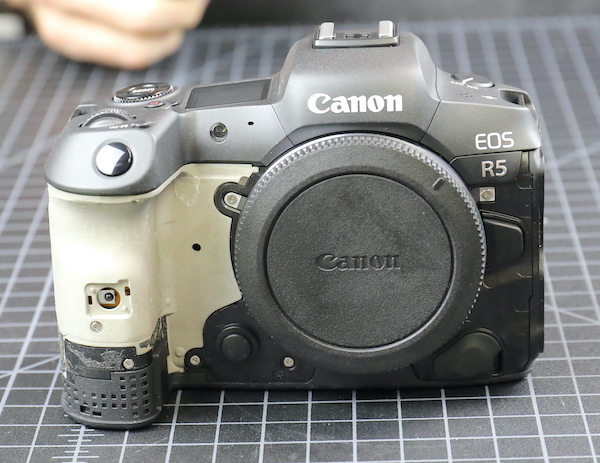
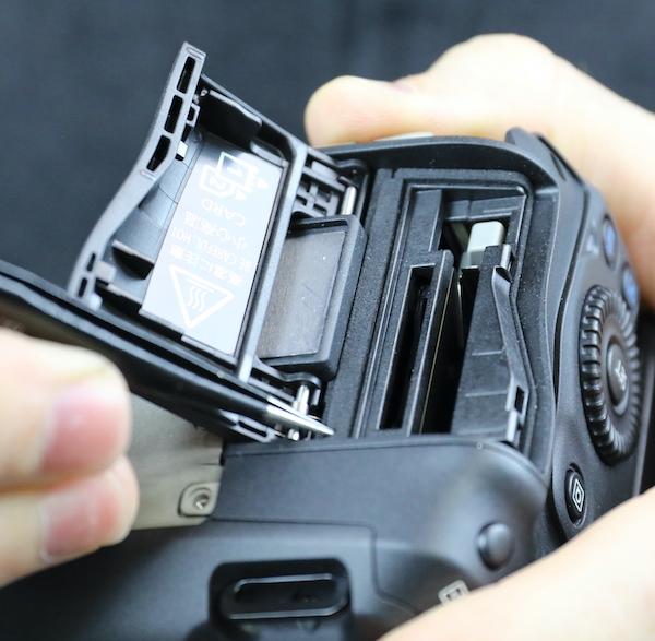
The camera looks pretty much like the other Canon cameras with the battery door off. That’s the connector for the WFT-R10 wireless transmitter, which is cool: It functions as a 2-battery grip plus provides ethernet as well as wireless connectivity, connecting up to 10 cameras to a server. This is not something I’m interested in myself; the onboard wireless is all I ever need. It seems a cool, albeit expensive, option for high-powered professional-type people.
Lensrentals.com, 2020
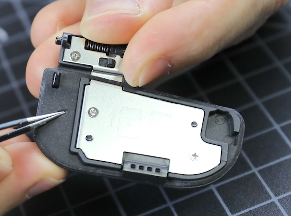
The battery door itself gives us our first pleasant surprise. In every camera, the battery door is a weak area for leakage. There’s usually some weather-resistant gaskets around the edge, which the Canon R5 has. In addition, the entire flat surface is soft gasket material in addition to the raised gaskets around the edges and hinge area.
Lensrentals.com, 2020
The viewfinder rubber comes off next, Canon attaches theirs with a couple of screws rather than a clamp.
Lensrentals.com, 2020
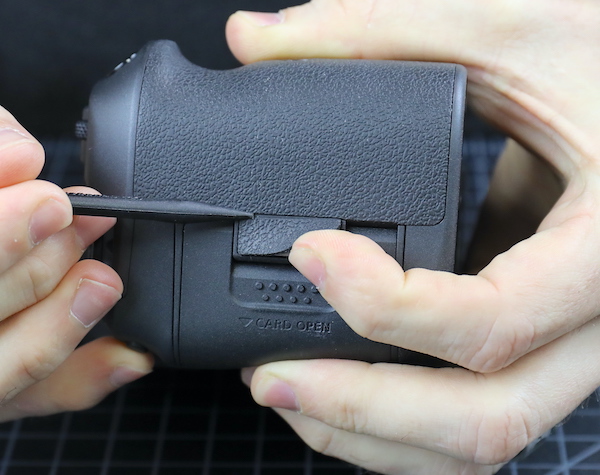
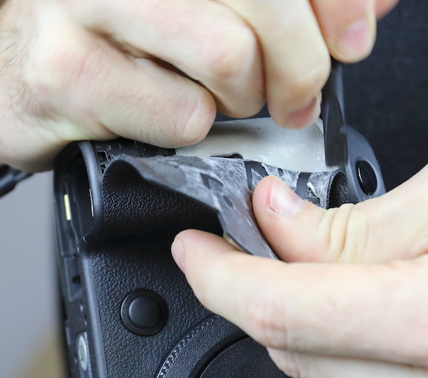
Next, of course, comes The Removal of the Grips.
Lensrentals.com, 2020
The key to taking off the grips, for those of you doing your own disassembly at home, is to keep as much of the double-sided tape on the grip as you can, which makes it easier to reapply. The grip material surface feels slightly different than earlier models to the touch, but it’s about the same thickness and flexibility.
Lensrentals.com, 2020
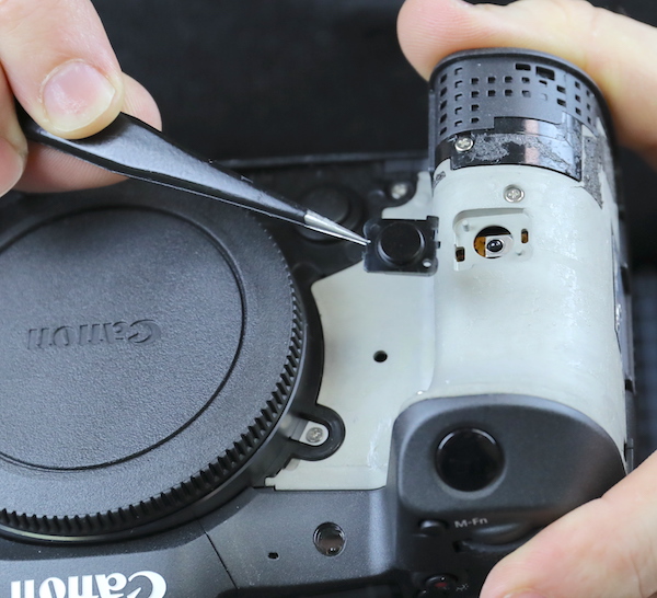
The cover to the remote control sensor is basically held on by the grip.
Lensrentals.com, 2020
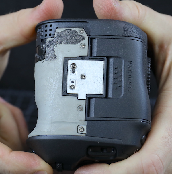
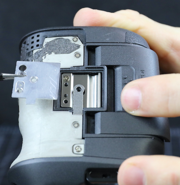
And there’s a metal plate covering the area of the card door hinge.
Lensrentals.com, 2020
It seems to provide some reinforcing strength, but mostly a smooth surface for the grip rubber to stick to.
Lensrentals.com, 2020
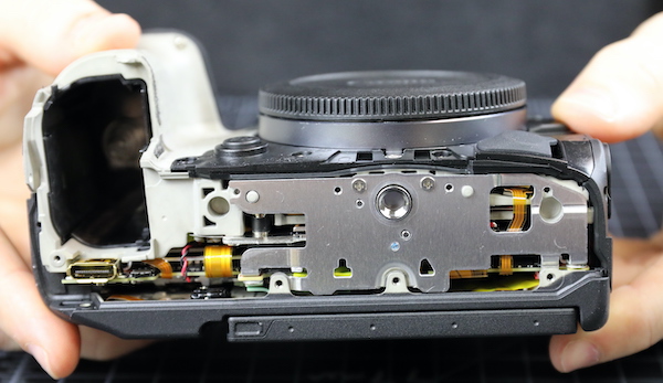
Now we have access to most of the screws and can start body disassembly.
Lensrentals.com, 2020
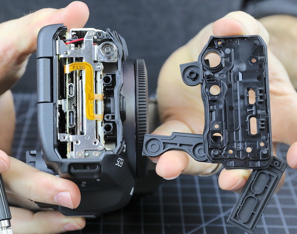
The bottom plate comes off next.
Lensrentals.com, 2020
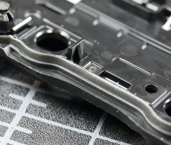
The inside of the bottom plates shows us a new thing! We’re used to seeing a bead of rubber felt between the plastic pieces of the body to seal for the weather. Canon now has a soft rubber gasket along the mating edge of the pieces. This is much larger and provides a greater seal area than what we usually see. It seems to be attached to the body (in the old days, I would have said ‘vulcanized’) rather than being glued on.
Lensrentals.com, 2020
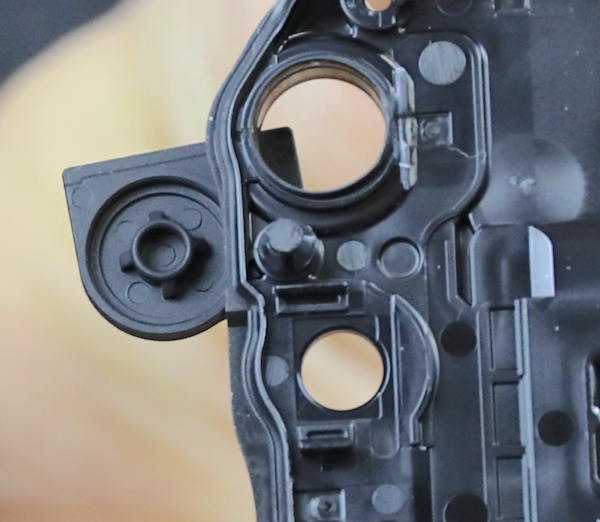
The same material is used around the openings where the plate seals around other parts. Here they’ve completed the seal for the battery door hinge from the inside.
Lensrentals.com, 2020
The metal tripod plate is sturdy and the actual tripod mount replaceable; both of these are things we consider important.
Lensrentals.com, 2020
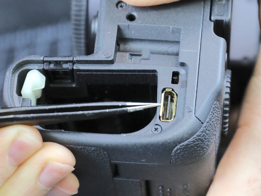
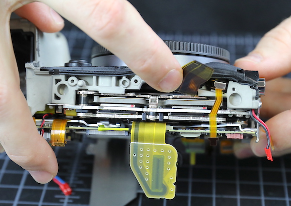
The I/O side comes off next, and again we see that big rubber lip sealing the entire piece. Also, note that both the HDMI and digital out ports are part of the main PCB, so secure your cables; tugging these ports loose will be an expensive main PCB replacement.
Lensrentals.com, 2020
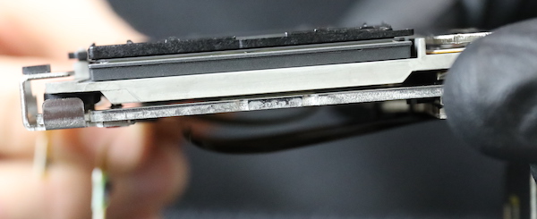
Another close up of the sealing gaskets from the side door. When we took these pieces apart, you feel the suction when they disengage. That’s not something we’ve seen in other cameras. The thing about weather sealing is it only takes one weak place to leak, but this sealing seems to be a step up from anything we’ve seen before.
Lensrentals.com, 2020
While there are gaskets around the I/O ports, with any port unless the covers are closed, you lose weather-resistant integrity.
Lensrentals.com, 2020
Under the card door, there is a thick foam similar to that on the battery door.
Lensrentals.com, 2020
And there’s that big rubber gasket where the door plates fit with the rest of the camera.
Lensrentals.com, 2020
OK, enough with weather sealing. You know weather sealing is outside my circle of trust, but I might put this within the rhomboid of reduced suspicion. I write off too many cameras from water damage every year to really trust weather sealing. This is good, but weather sealing isn’t about where it is good; it’s about where it can leak.
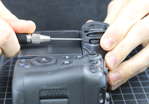
The next step is to take out the diopter adjustment screw.
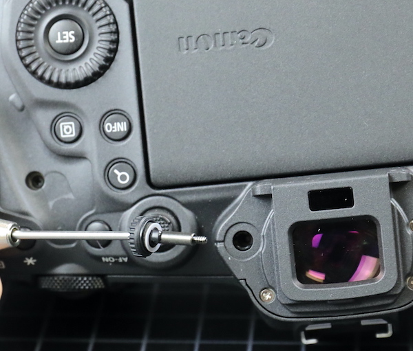
Lensrentals.com, 2020
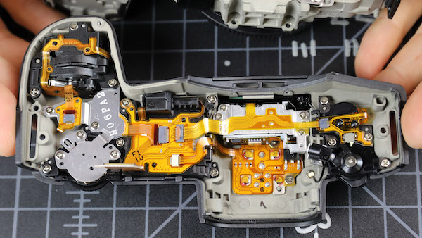
And then the back assembly comes right off.
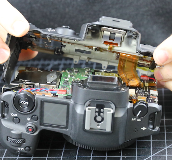
Lensrentals.com, 2020
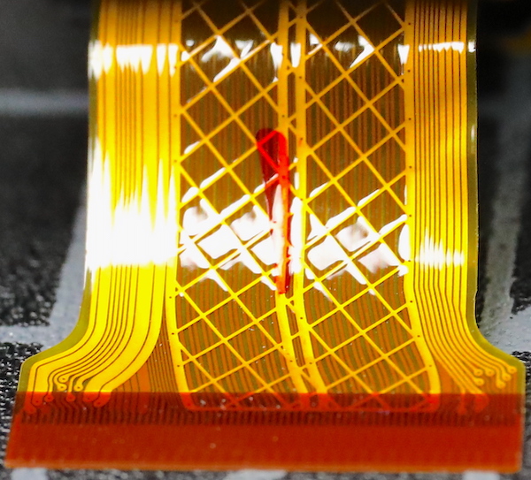
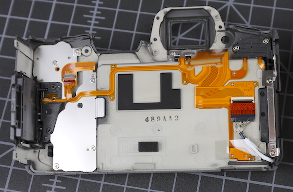
The back has more dials than the original R, but the LCD wiring appears identical; nothing much to see here. Except for the new, coppery colored flex they’re using on the LCD side, but not the switch side. I don’t know why the new flex material, but it is pretty.
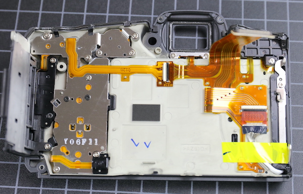
Lensrentals.com, 2020
As you can see above, a Canon tech made his ink marks when this part passed inspection. Aaron decided to leave his mark of approval, too.
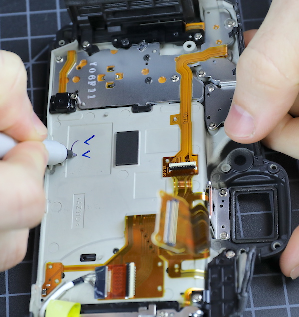
Lensrentals.com, 2020
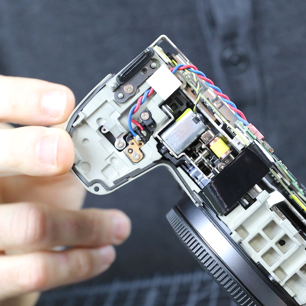
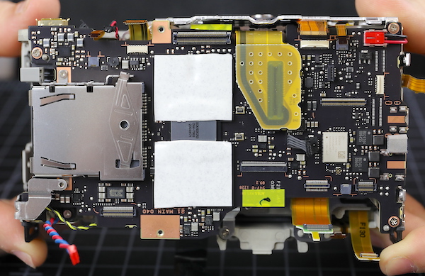
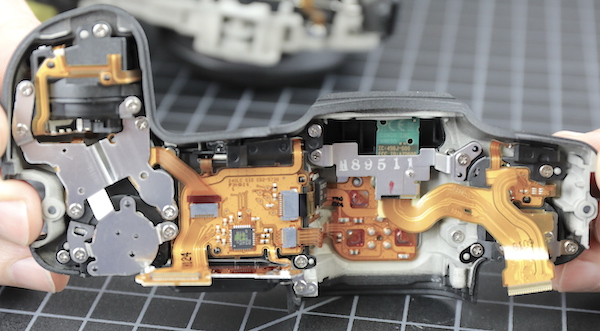
Now we can look into the camera and see the back of the circuit boards. This is immensely more intense and dense circuitry than we saw in the R. First of all, there’s a green sub-board that appears to be about DC power conversion. You can see some hefty wires entering it from the battery compartment. The larger, square chips are TPH8R903NL voltage converters. Over to the left on the black board, the large white chip is a Canon WiFi chip with what looks like an antenna plugging in just above it.
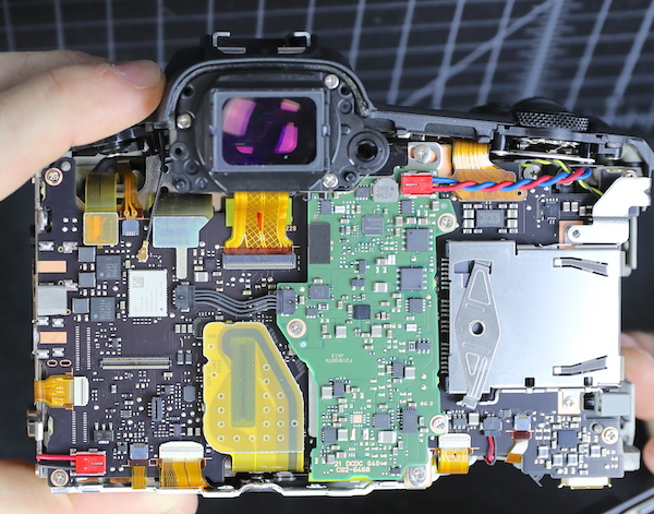
Lensrentals.com, 2020
I am NOT an electronics expert, but I do know DC-DC conversion boards have to generate waste heat. How much depends on load, but I’m told 10%-20% of wattage isn’t unusual.
The viewfinder comes out next.
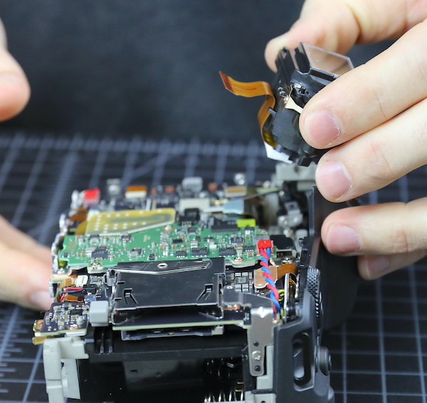
Lensrentals.com, 2020
I’ll indulge in my flex fetish and show you a closeup of ‘the argyle flex’. We actually decorate our office with large printed macros of pretty flexes and circuit boards. Yes, I know I need some counseling.
Lensrentals.com, 2020
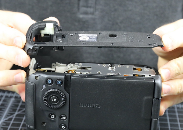
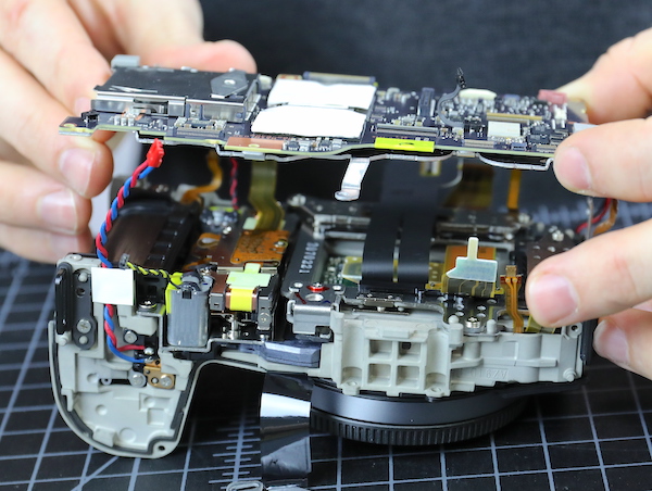
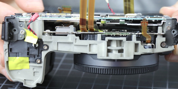
Anyway, with the viewfinder out, the top assembly comes off. Not much different, other than the number of buttons and dials, from the other R top assemblies. Except they’ve put all the connections between the top and motherboard in a single flex; usually, there are several. There is also, compared to the main part of the camera body, a bit of air up here.
Lensrentals.com, 2020
The weather sealing is different around the top assembly compared to the rest of the camera. Where we had those hermetically rubber seals along the bottom and sides, we don’t see them on the top. On the top assembly, there is the traditional ‘top plate sticks out over the body plate’ thing.
Lensrentals.com, 2020
With the standard foam sealing strips over some of the body plates. So we have the regular overhang and foam sealing on top that gives rain protection, but the bottom, the part you might set in a puddle, is tightly sealed. It makes sense unless we missed a leaking point on the bottom.
Lensrentals.com, 2020
There’s not much sealing material over the lens mount area, though, so if there’s a weak point in weather sealing, I guess this would be it.
Lensrentals.com, 2020
TOTAL SPECULATION: Maybe the looser sealing at the top, where heat rises, helps heat get out. The chassis is not a huge heat sink, and it’s wrapped in insulating rubber grip material. It radiates heat, of course, you can feel it, but that’s not an uber-efficient way to get rid of heat.
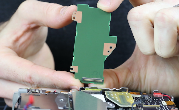
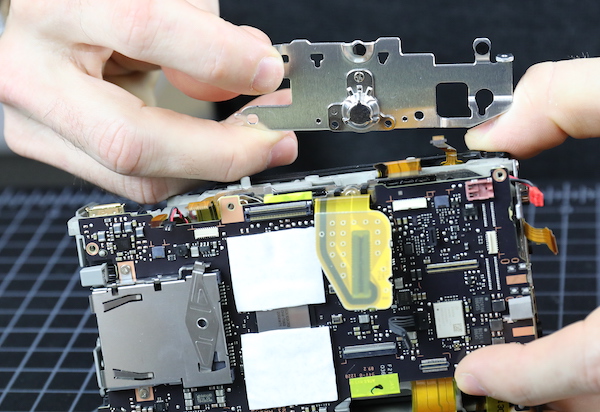
Now we turn our attention back to the main body. That accessory board comes off easily. It’s a single surface board; the backside is smooth.
Lensrentals.com, 2020
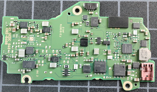
And a single view for those who do chip quests.
Lensrentals.com, 2020
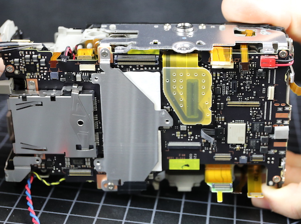
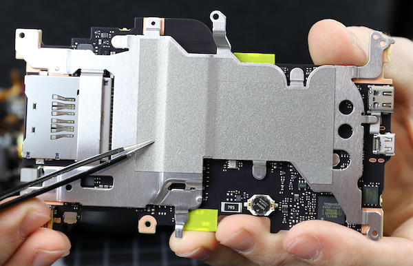
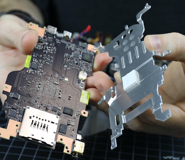
There’s an aluminum heat sink or electronic shield beneath that board.
Lensrentals.com, 2020
Electronic shields tend to be quite thin, but this is a manly piece of aluminum, 0.98mm thick. I speculate it’s more about heat than electronics. Notice I said ‘speculate’.
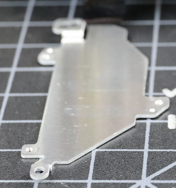
Lensrentals.com, 2020
The aluminum shield connects to copper tracings at the top and bottom (and the bottom tracing connects to the metal base plate), plus it sits above the two thermal pads, so I’m feeling pretty comfortable that this transfers some heat.
Lensrentals.com, 2020
Peeling back the heat transfer pad shows the four SKHynix SDRAM chips we’ve already been told are there surrounding the main CPU.
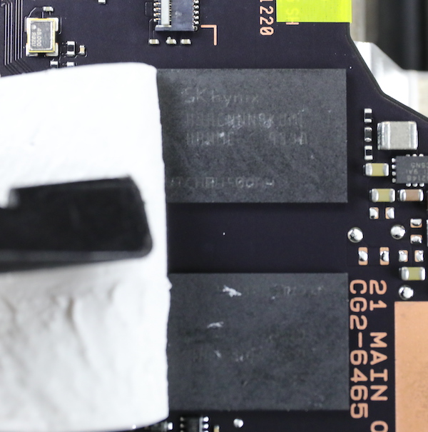
Lensrentals.com, 2020
We took off the tripod plate next (note, we had to take off that top heat sink before the tripod plate, so they are indeed connected). Notice the tripod socket is screwed, not soldered, to the plate, so it’s easy to replace.
Lensrentals.com, 2020
Now we can get a glimpse of the stabilizer/image sensor arrangement. There’s not much air down in there, particularly if you compare it to the original R.
Lensrentals.com, 2020
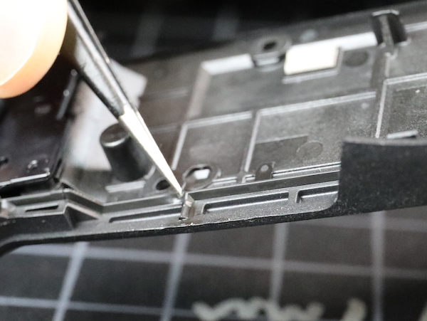
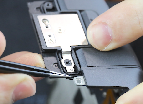
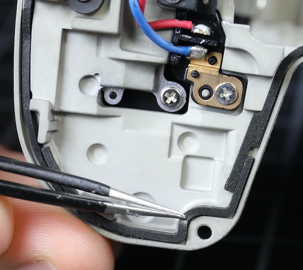
As long as we’re looking around the edges, I should show you the battery door switch, since people have been having a grand old time stuffing things in there to make the camera think its door is staying shut. This is a small, frail switch soldered directly to the motherboard and only held on by the solder. I have it on very good authority (my own) that it’s easy to dislodge the switch from the circuit board with just a little bit of torque, requiring a complete mainboard replacement, which is very pricey.
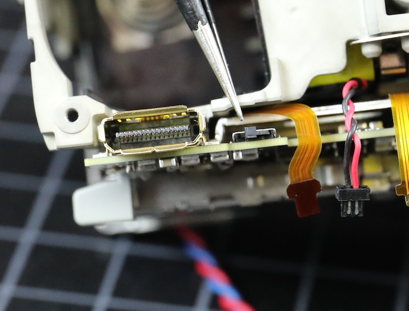
Lensrentals.com, 2020
Having completed our camera body tour, we took out the main PCB.
Lensrentals.com, 2020
There’s another big aluminum heat sink on the underside. This one has a layer of electronic insulating tape over the sensor.
Lensrentals.com, 2020
Removing this shows another thermal pad underneath the CPU. So it seems Canon is sending the heat from the SDRAM chips to one sink, and from the CPU to another. To some degree. (Get it? Degree?)
Lensrentals.com, 2020
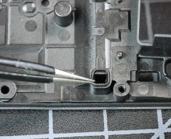
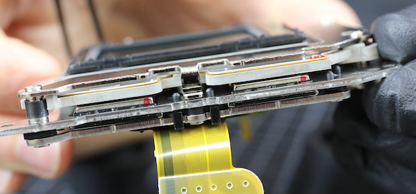
Both card slots are part of the main PCB, but we can remove the ejection mechanism for the CFExpress card, getting a look inside. Here you go; a picture of the inside. You can see why we think CFExpress is a lot sturdier than the long, bendable pins of old CF card slots.
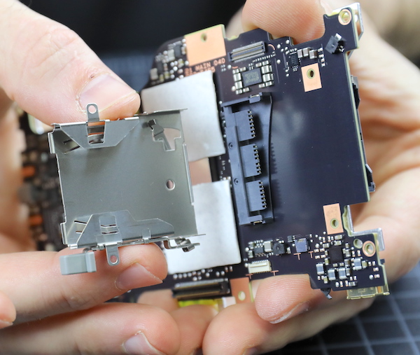
Lensrentals.com, 2020
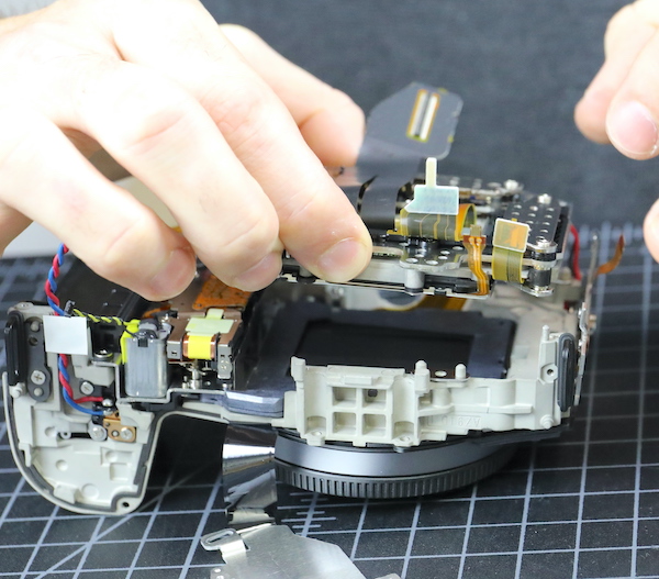
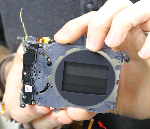
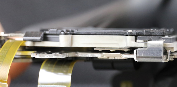
Going back to the camera, we get to see the back of the sensor / IBIS assembly and the huge flexes leaving there, as well as the shutter mechanism between the sensor and the battery compartment.
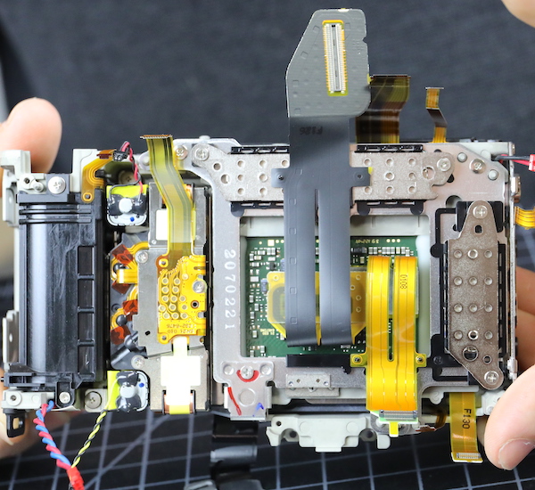
Lensrentals.com, 2020
The sensor assembly is held in by three screws. As you can probably see, Canon has changed to shimming the sensor for flatness (in the R they used spring tension screws). Spring tension screws can theoretically be more accurate (depending on how accurately they measure), but I assume the vibration of an IBIS unit could loosen them over time; every IBIS camera we’ve opened uses shims.
Lensrentals.com, 2020
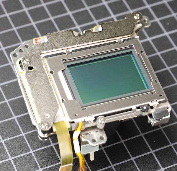
The sensor / IBIS unit comes out as a single piece.
Lensrentals.com, 2020
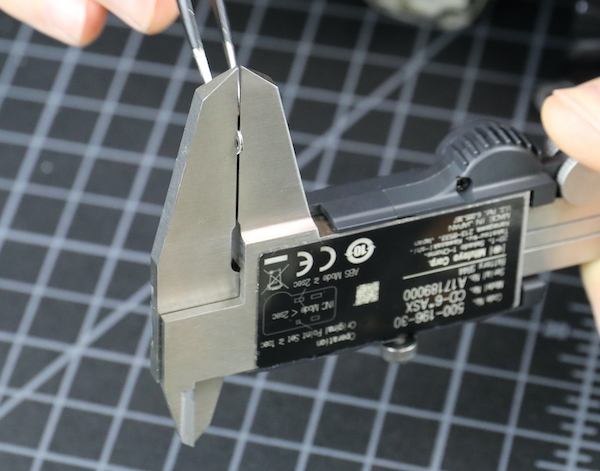
Lensrentals.com, 2020
The shimming for this one was 0.45mm, 0.45mm, and 0.24mm, so a pretty significant tilt compensation was made. And no, that’s not unusual for any camera.
Lensrentals.com, 2020
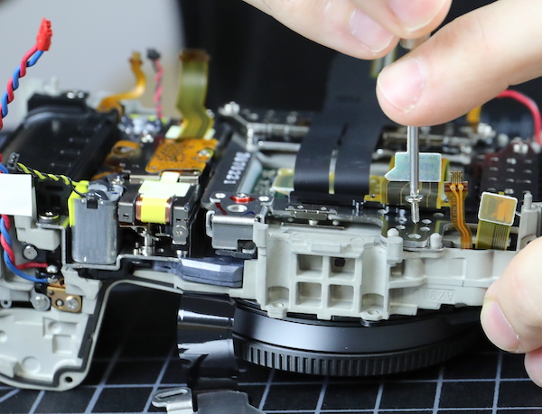
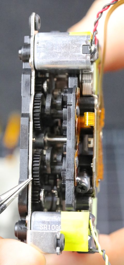
The only thing really left in the chassis is the shutter assembly, which is held in place by screws and posts.
Lensrentals.com, 2020
Lensrentals.com, 2020
These we don’t take apart, but then neither does the service center these days. Nobody’s got time to line up all the gearing, plus if you mess with it, you have to have factory software to recalibrate the timing.
Lensrentals.com, 2020
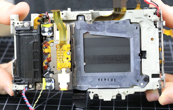
With the shutter out, the chassis really has nothing left inside but the lens mount, battery case, and a few connection traces. You know something I’ve found interesting in all the jumping-to-conclusions about heat inside the Canon R5? Not one person has tested the heat conductivity of the chassis. (Spoiler alert: it doesn’t conduct heat well.)
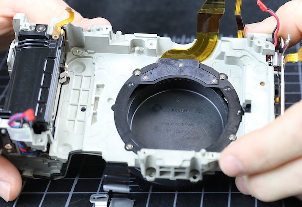
Lensrentals.com, 2020
Outside of the chassis sits our sensor and IBIS unit, which I’m quite interested in.
Lensrentals.com, 2020
We aren’t going to get majorly aggressive here, but we’ll take off the cover plate.
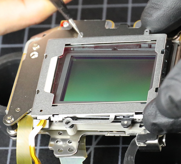
Lensrentals.com, 2020
Which comes off easily along with the outer self-cleaning glass plate.
Lensrentals.com, 2020
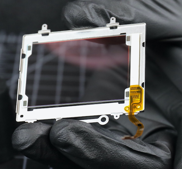
We can’t get an exact glass measurement without taking the sensor apart, and we have a bad habit of breaking glass when we do that, so it will have to wait for the first Canon R5 to die for a more accurate measurement. We estimated the total (including the front piece) at about 2mm, which is Canon standard.
Lensrentals.com, 2020
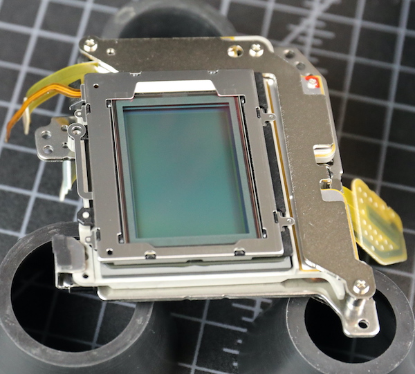
I also wanted to look at how the sensor is supported in the IBIS unit. We’ve found some fractures in cameras where the sensor is supported by several screws-through-plastic-tabs. There is one screw tab you can see above, but that was mostly for the cover plate.
On all the edges of the Canon unit, the sensor is mounted directly to IBIS plate; no tabs. That doesn’t mean it can’t break, of course, or glue come loose. But this seems sturdier to me.
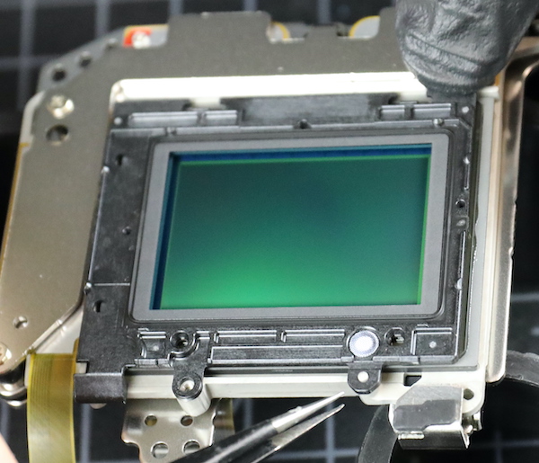
Lensrentals.com, 2020
Lensrentals.com, 2020
On the IBIS itself, we can see the permanent magnets; the electromagnets are shielded here, so not completely obvious.
Lensrentals.com, 2020
So What Did We Learn Today?
Not much that was surprising. What with the IBIS unit and a more intense chipset, the camera is pretty thoroughly filled up, there are lots of parts and not much air. There’s a new weather sealing method in the lower 2/3 of the camera that seems to give a really, really tight seal. And there we some pretty new flexes which matters not a tiny bit to anyone but me.
The IBIS unit is very compact but well-engineered. There are no tab connections that might be weak points; the sensor is connected to a flat plate around all its edges. That doesn’t mean there can’t be problems, of course, this is a new build, so we won’t know for a year or so.
There seem to be two separate heat sinks, one under the voltage board, another between the main PCB and the sensor assembly, with thermal pads to direct heat to each. At least one of them connects to the tripod plate, which might provide a secondary sink. This is a lot of heat sink compared to most photo cameras, but not even a fraction of what we see in a video camera. What I can’t tell from this is how that heat then gets out of the camera. It’s sure not air circulation.
Given how tightly sealed things are, I’m curious as to where the heat goes to get out of the camera; some further investigation is required there. A lot of people are talking about how the heat should move around inside the camera, slapping some thermal paste around, and doing things to manipulate the heat cut offs.
I’m a simple person. All I can think of is, ‘how does the heat get out of the camera?’ Sure it goes into the metal sinks, but once they heat up, then where? In a small photo camera, there’s not a lot of ventilation/convection current to get let the heat out. This camera is better sealed than most; I doubt there’s very much ventilation at all.
Somebody should look into that.
Roger Cicala and Aaron Closz
Lensrentals.com
September, the ninth year of 2020
Author: Roger Cicala
I’m Roger and I am the founder of Lensrentals.com. Hailed as one of the optic nerds here, I enjoy shooting collimated light through 30X microscope objectives in my spare time. When I do take real pictures I like using something different: a Medium format, or Pentax K1, or a Sony RX1R.
-
Brandon Dube
-
Roger Cicala
-
Olandese Volante
-
Roger Cicala
-
Athanasius Kirchner
-
Athanasius Kirchner
-
Nick
-
Zak McKracken
-
Foma Akvinat
-
Olandese Volante
-
Olandese Volante
-
Roger Cicala
-
Roger Cicala
-
Roger Cicala
-
Olandese Volante
-
Olandese Volante
-
Shane Castle
-
Kai Harrekilde-Petersen
-
Scott
-
Roger Cicala
-
Glenn Ruhl
-
Scott
-
Michael – Visual Pursuit
-
RNG
-
Brane212
-
RNG
-
RNG
-
Scott
-
RNG
-
RNG
