Equipment

OLAF’s Lens Art

Published April 18, 2014

This is a Geek Article, with very little practical information. But there are pretty pictures that non-Geeks might like. (Not the construction pictures, the ones further down.)

First, I should explain why I haven’t posted much lately. Lensrentals was able to expand into some adjacent space, which was desperately needed. But the testing and repair departments were moved and expanded into the new space. Over the last 10 days the second testing area went from this . . .
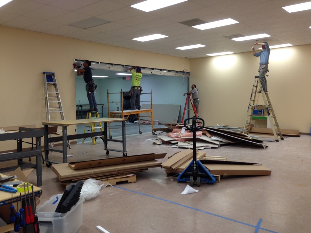
to this.
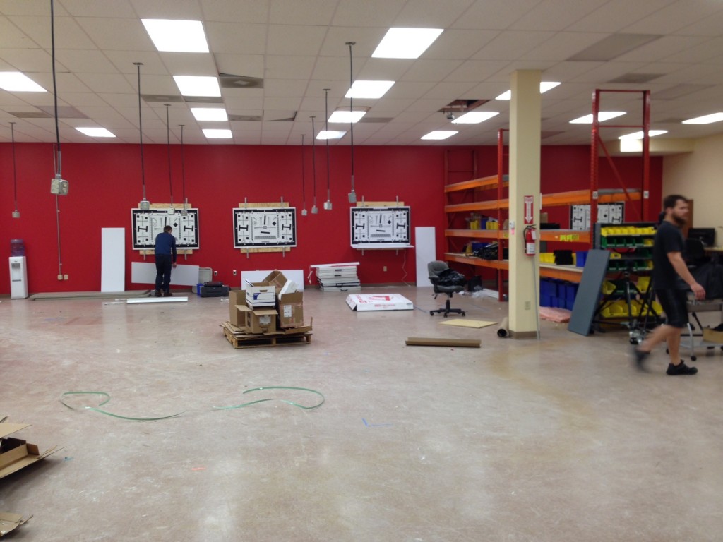
To this.

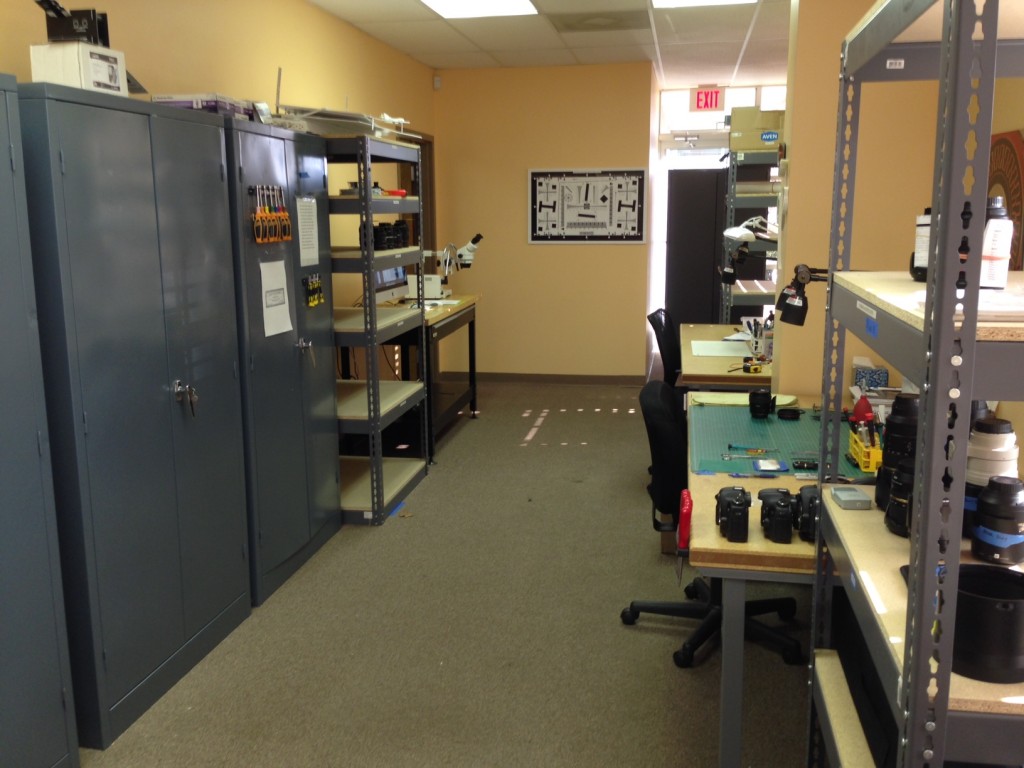
We were finally able to get some new repair workstations set up.
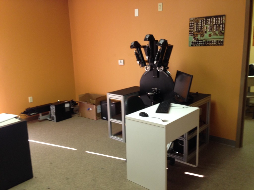
And moved OLAF to his own room where he’ll be joined shortly by our new MTF bench.
Pictures from OLAF

We did manage to squeeze in some time with OLAF to explore his capabilities a bit – although we aren’t done with that by any means. One of the first things we needed to do was set up standards for various lenses. Basically, this means testing known good and bad copies of different lenses so we can see what the reversed point spread images from OLAF should look like, and what they look like for different types of misalignment.

People like to think that adjusting a lens just means turning a knob somewhere and making all of the the points nice and sharp. That is sort of true in the very center of the lens (not the turning a knob part, but making the central point nice and sharp).
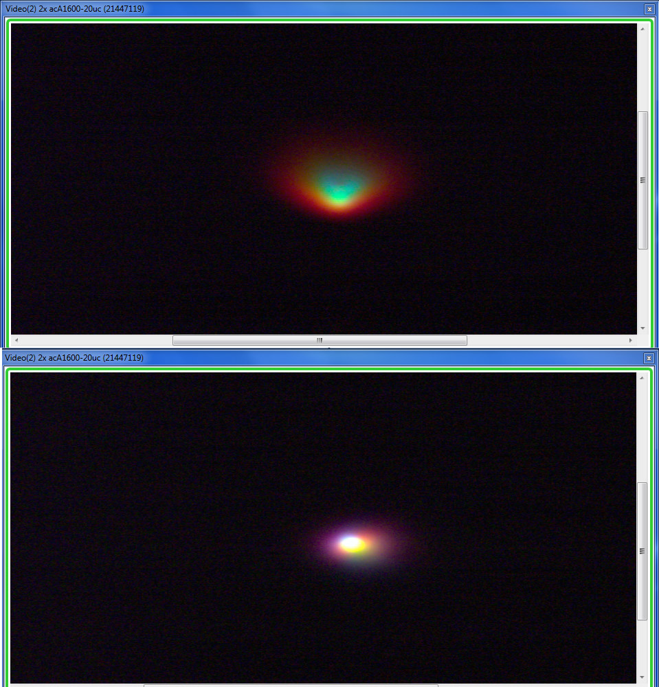
Right at the center, every lens is capable of resolving a clear point. This image shows the center point of a lens before (top) and after (bottom) adjustment.

For a few lenses, like the Canon 50mm f/1.2 L and Nikon 70-200 f/2.8 VRII, sometimes that’s all that’s needed. OLAF is a champ with this kind of thing and lets us do these adjustments in minutes rather than hours.

Unfortunately, centering one element is not the most common type of lens adjustment. Other adjustments require evaluation of things away from the center (properly called “off-axis”). Once you’re away from the center, five micron points don’t look much like points, even with very good lenses that are well-adjusted optically. In theory, a lens designer can calculate out what the various aberrations for a given lens should make a point look like off-axis.
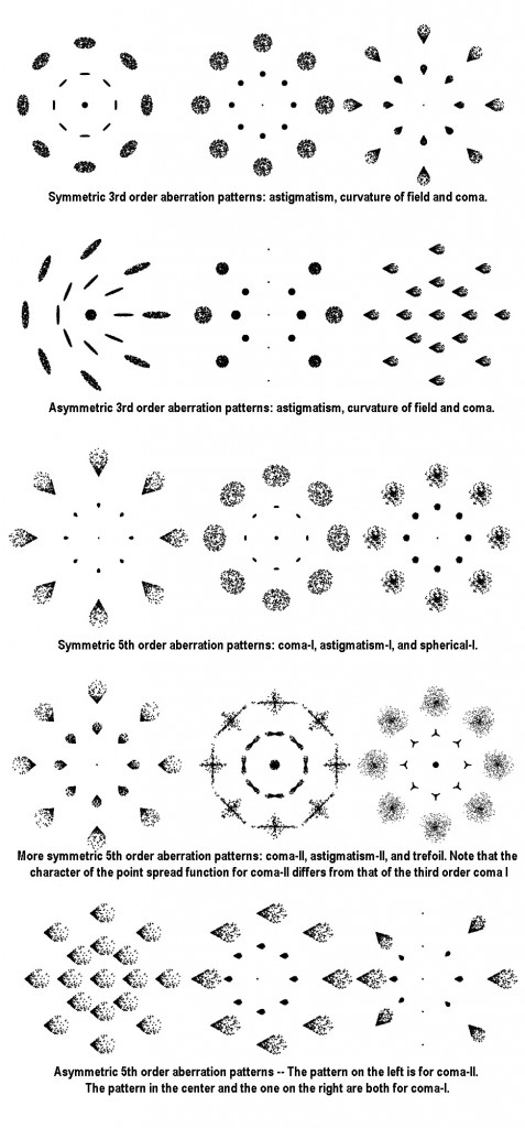
The above patterns taken from “Generic Misalignment Aberration Patterns and the Subspace of Benign Misalignment” Paul L. Schechtera and Rebecca Sobel Levinsona. Catchy title, isn’t it?

In reality, you don’t get one type of aberration at an off-axis point. You get a combination of several. Sometimes the lens designer uses one aberration to counteract another. Sometimes there will be two or three small aberrations instead of one large aberration, etc. Plus, when a lens has a decentered, tilted, or misspaced element, things get really interesting. The end result is that off-axis points on a real lens usually don’t look like any of the above patterns, especially when you look at them in color and can also see chromatic aberrations.

We just take the brute force approach, checking half-a-dozen known good copies of each lens to see what the off-axis patterns should look like, then compare that to the misadjusted lenses. While our database is far from complete, I find it fascinating to see how different lenses ‘interpret’ a point of light off-axis. It’s rather pretty, actually, so I thought I’d share a few images.
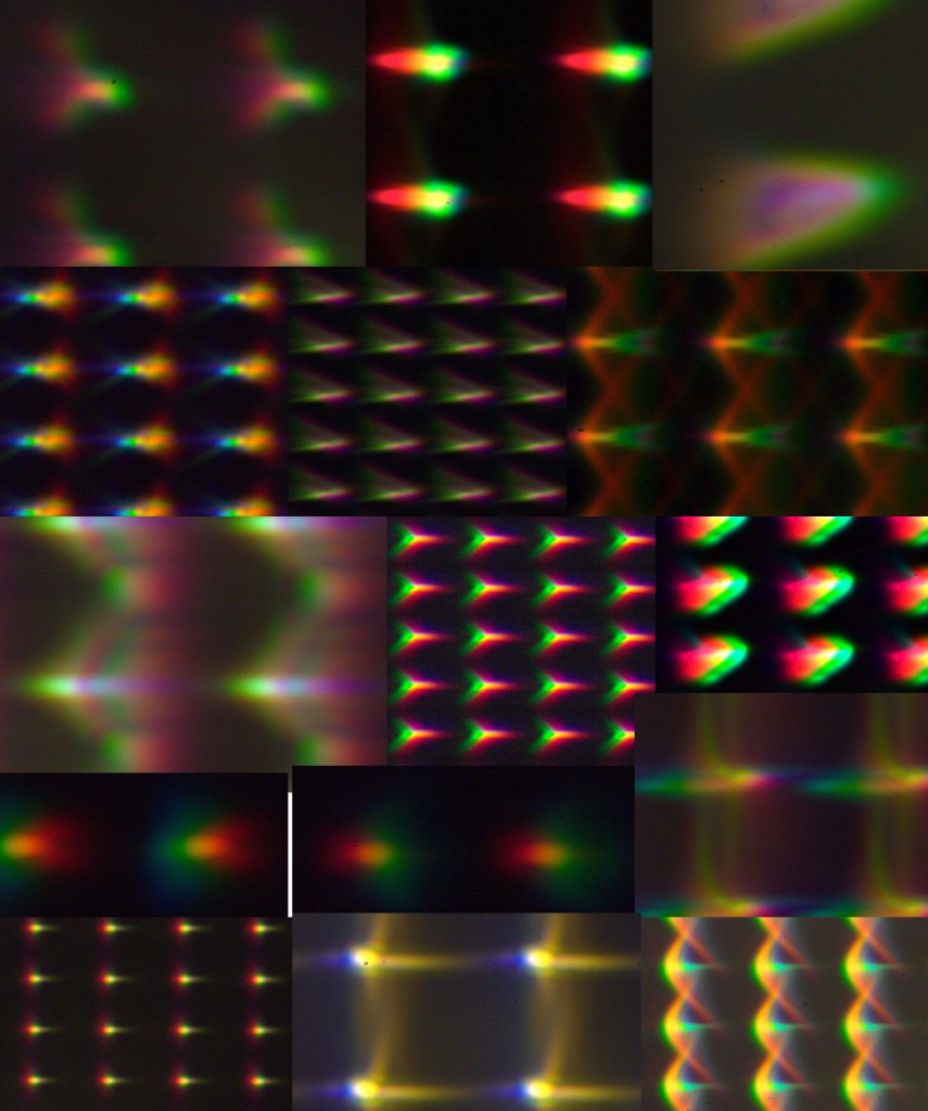
What points near the edge of the frame look like for various lenses. When there are fewer, larger points the lens is wider angle (16 to 24mm in this picture), while smaller, closer points are longer lenses (70mm to 100mm). 


The ‘points’ above are along the lateral edge of the field, from good-quality, well-adjusted lenses. Every one of those lenses resolves a nice round point in the center just like the ‘adjusted’ lens in the image above. This is what the ‘point’ looks like along the lateral edge. (These were all focused for the edge, so field curvature isn’t playing a part.)

Before you run screaming into the hills, remember these are magnifications of five micron points of light. Plus, the way OLAF is made overly enlarges the points of wide angle lenses, so those seem a lot worse. Also remember the pixels on your camera are likely larger than five microns, so a lot of the smearing you see at this magnification isn’t particularly meaningful.

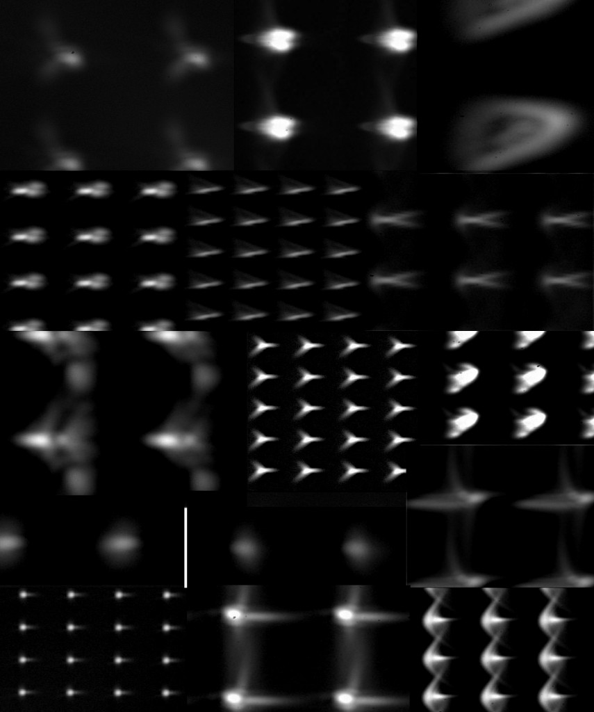
If I take that image above, convert it to black and white, and reduce the dynamic range about 25% in Photoshop, it looks more manageable. In fact, if you scroll back up, it looks a bit like some of the textbook pictures of various aberrations. Especially when you consider that most lenses have more than one aberration affecting off-axis points.
 

Anyway, the picture above showed a lot of apple-to-oranges comparisons – those were very different lenses. Looking at the outer pixels for some similar lenses gives an interesting apples-to-apples comparison. Below are right side pixels from half-a-dozen 35mm focal length lenses.
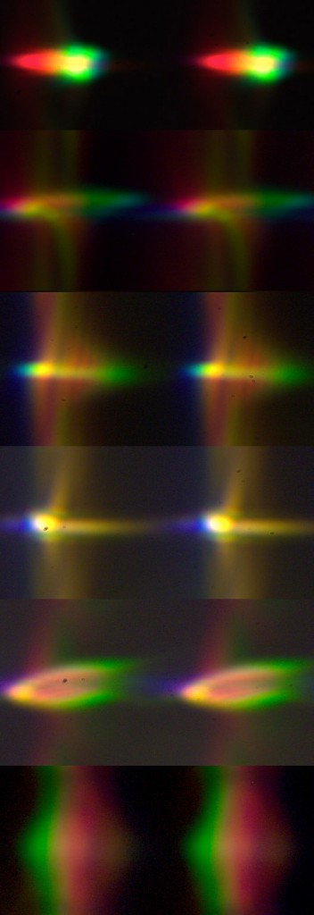
Top to bottom: Sigma 35mm f/1.4; Canon 35mm f/1.4; Zeiss 35mm f/1.4; Canon 35mm f/2 IS; Samyang 35mm f/1.4; Canon 35mm f/2 (old version)


Here are lateral edge points from four different 50-something mm lenses.
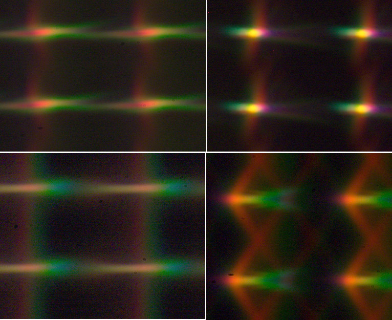
Clockwise from top left: Nikon 58mm f/1.4; Zeiss Otus 55mm f/1.4; Canon 50mm f/1.2 L; Zeiss 50mm f/1.4. All were shot at widest aperture, so the Canon 50mm f/1.2 is at a bit of a disadvantage.


I don’t think this is important data for evaluating lenses, or anything. But it is kind of interesting to see how a lens renders a point of light off-axis. I tend to roll my eyes a bit when I hear someone say, “This lens is just as sharp in the edges as it is in the center,” because no lens is. Ever. This explains why I prefer to shoot my subject in the center of my image and then crop for composition. I can tell myself those off-axis aberrations don’t really affect the image much — but I still know the round points are all in the center. Sometimes being a Geek has disadvantages.

On the other hand, looking at this you’d think no lens could ever resolve anything recognizable at the edge of the image. So just for fun, I took the 50mm images above, put them in Photoshop, converted to luminance channel, and knocked off the top and bottom 30% of the luminance with the levels command in about 14 seconds. Guess what the images above look like now? Yeah, they’re pretty much points. This is a simple kind of thing that any modern camera could (or does) do in firmware or we can easily do in postrpocessing.


Does this have any point? Maybe a bit. For example, if you look at what a point looks like near the center of the image compared to one near the edge, you may understand why I’m such an advocate of using masks when I sharpen or otherwise post-process an image. I usually want more effect out near the edges and less near the center. Below are images for a central point and a lateral edge point for four lenses, all of which are optically good copies of what are considered excellent lenses. It doesn’t seem logical I’d want to apply the exact same manipulation to each.

This also demonstrates why in-camera image processing is becoming so popular with manufacturers. It’s pretty simple, with a lens database in place, to process the images so that they look better than they would without specific processing.
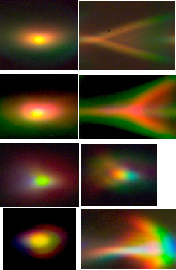
The central point (left side) and one from the lateral edge (right side) for four different lenses.


We Do Really Use OLAF

Ok, the pictures and stuff are fun, but that’s not why I bought this machine (although the pictures are a nice side benefit). I bought it to adjust decentered lenses. For adjustments, all of the chaos of different patterns isn’t particularly important.

In addition to making the center point nearly a point, we get to look at the two sides and compare them. If the sides don’t look about the same, the lens isn’t quite right, even when the center has been adjusted to a nice point. Below are images comparing the left and right points from three different lenses. It’s pretty obvious that the sides aren’t alike and therefore the lens is optically out of sorts.
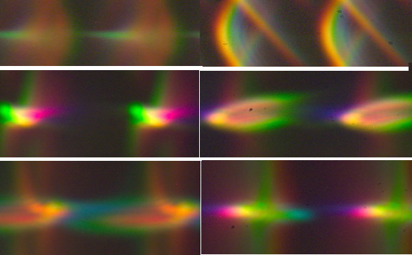
 

For the middle and bottom images, the points on one side are good and we simply need to get the opposite side to match. The lens in the upper image is really in a bad way and neither side looks anything like it should. This is when we pull up a saved file of what the lens should look like so we know what we’re trying to get to.

Of course, once we’ve got the two sides improved, we have to rotate the lens to several positions and make further adjustments until it’s the same in all quadrants.

It’s simple, although it’s often not easy. Each lens has different adjustable elements and each adjustment has different effects. Some lenses still take us hours to adjust properly. But being able to do those adjustments while we watch has reduced our optical adjustment times by 50%, which is a really big deal. Even more importantly, we’ve been able to correct a dozen lenses that neither we, nor the factory service center were able to adjust at all before.

It’s early in the learning process, so I can’t say with any certainty that OLAF is the universal answer to optical adjustments. But it’s certainly going to be a big help. More than that, though, it’s helping us learn more about lenses, so it’s already worth the money.


Roger Cicala

Lensrentals.com

April, 2014

Author: Roger Cicala

I’m Roger and I am the founder of Lensrentals.com. Hailed as one of the optic nerds here, I enjoy shooting collimated light through 30X microscope objectives in my spare time. When I do take real pictures I like using something different: a Medium format, or Pentax K1, or a Sony RX1R.

Posted in Equipment
  • John C

    Roger, I have some bad news for you. The width (and height) of a pixel on a 24 Mpix camera is 4 microns (micrometers)…

    John

  • Roger Cicala

    Max,

    In theory, if we had the actual optical formula for a lens (curvature, spacing, and glass type) for each lens we could put it into one of the lens design programs and get a mathematical model of what ideal would be. Then if we were really bright, we could calculate distance from center, plug in each of those aberrations, do the calculations for each one, overlay them, and have an idea of the what the point should look like in the ideal lens. Of course, then we’d have to go back find acceptable range of variation for each element (because perfect only happens in computer programs), redo all the calculations overlay all the various combinations of those calculations and get a picture of what the point would look like for a realistically good lens.

    In reality, we grab 6 or 8 known good copies, put them on OLAF, and take pictures so we know what it should look like.

    RC

  • Max

    Hi, Roger!

    Of course OLAF is a great tool for getting information from real instance of lens, but as far as I understand it doesn’t tell you anything about how should look reference image. In other words it doesn’t tell how close this tested instance to mathematical model of it’s optical scheme. It’s obvious that even mathematical model should have some aberrations and reference image would not look like simple grid of dots.

    So it’s quite interesting how do you see (or calculate) how close tested instance to it’s mathematical model? Do you have some software which can render pictures similar to OLAF’s but use only mathematical model of optical scheme? Or you simply define best instance of lens as reference?

    Best regards, Max

  • Roger Cicala

    Hi Graham,

    Every type of lens is different qand we’ve learned some tendencies with many of them. But also every copy of a given lens is different. We often get some hints – for example, the center point tends to smear with decentering, all points tend to smear with spacing problems, and tilt messes up the sides with less effect on the center. With zoom lenses certain adjustable elements may effect the long end more than the short end, etc.

    But adjusting one thing often messes up another, so we often find fixing a tilt problem at the long end makes a decentering at close focal lengths, fixing that makes the tilt change again, etc. etc. Then when we have it looking great on OLAF (which works at infinity) we Imatest it at 15 feet and find there’s a problem there. This is why it can take so long. It’s also why I’d pay good money to get my hands on some factory service manuals that would clarify which adjustments have which effects. For example, we’ve probably spent 80 hours with Canon 16-35 lenses just figuring out the algorithms for which adjustments have which effects and what other adjustments each adjustment messes up.

  • Graham Stretch

    Hi Roger.
    Thanks for the very informative posts, I’m learning so much about lenses. I have that enquiring minds need to know thing going on but only just found out from you that I would like to know, do you adjust all types of lenses in the same order, ie centre sharpness first then move on to check and adjust for decentered elements or are some lenses done in the reverse order to other lenses, is that dependant on type zooms in one order primes in another, or by manufacturer, canon one way Nikon the other, just random depending on ease of access to each adjustment.
    Oh what order would the adjustments be made, or is that something that you have worked hard to learn that gives you a commercial advantage that you wish to retain? BTW I fix cars not lenses so it won’t help me!
    And yes I got the date thing even though you put it right, I like your reasoning for the correction too!
    Thanks again,

    Cheers Graham.

  • Roger Cicala

    Thank you Kai, got that fixed. Another accidental Cicala invention. Like Mark Twain said, “Never trust a man who only knows one way to spell a word.”

  • Kai Harrekilde

    Roger,

    What’s a “roung point” – another Cicala invention? 😀

  • CarVac

    I realized something useful: you can compare directly the angular resolution of lenses, regardless of focal length (think telephotos) by comparing the size of the points.

    Of course, on the superetelephotos that this is more interesting for, the aperture of the collimator is smaller than that of the lenses. But it would probably work for things like comparing a naked 300/4 to that with a 1.4x teleconverter.

  • Thanks to both Roger and CarVac for pointing out my fundamental error. I though the collimators where at the top and the “viewer” was at the bottom. So at “the sensor” (the focal plane) the spots are are always 5 micron in size.

    I was time reversed 🙂

    Now I get it.

  • Roger Cicala

    Norm, we’ve been doing this stuff for several years, and a readjusted lens is no more likely to get out of whack than a lens that’s never been adjusted.

    Things we sell through Lensauthority.com are all tested, but not necessarily adjusted. We are starting to pick out some especially sharp copies, though, and listing them as such.

  • Roger Cicala

    Paul, we have to repair about 600 items a month.

  • Roger–thanks for the post, and it’s great to hear your business is booming! I’m amazed that you do that much repair work. That’s a pretty serious facility you have there. Does the stuff you rent get banged up that much? Thanks—Paul

  • NormSchulttze

    It will be interesting to see if lenes that have been tuned up remain so. That will take some time to be revealed, but it would be useful data.

    And, are lenses that are being sold run thru OLAF and tweaked, if needed ?

  • David Miller

    This is very beautiful. As a photographer I’m not sure how much I care about this — a bit, I guess, but I’d rather have knowledgable people taking care of it. However, as someone who is intensely curious about how the world works, I am enthralled!

    Thank you Roger, for putting me in touch with my Inner Geek.

  • While scrolling through the ’35corners’ I immediately thought: “That top one is the Sigma 35mm f/1.4!”
    Granted, that was pretty obvious… 😉

  • Roger Cicala

    CarVac you got it!

  • CarVac

    In hindsight:

    OHHHHHHHHHHHHHHHH.

    Since the wideangles have more widely spaced points, according to the description of the big collage, then this is actually projecting point lights through the lens, and capturing what comes out the front with the collimators.

    Thus, this isn’t the image of what appears on your sensor from a point light source in the real world, but instead, a map of what a given point on the sensor receives light from.

    And now I understand how you can resolve these structures without some future-tech ultra-high resolution sensor.

  • CarVac

    Clearly OLAF has an image sensor somewhere, because you’re getting an image out.

    Is it magnified first with optics, and then fed to a sensor, or is this something like a cellphone sensor with ridiculously high pixel density that can easily outresolve the lens?

  • anon

    Okay Roger, I love you how you are … ;-)))

  • Roger Cicala

    I know, but people who read this will get it. They know how bad I am with typos and dates. Monday when the reposting sites pick it up I want it to look as semi-professional as it can 🙂

  • anon

    Hi Roger, thanks for your replay. But you have changed your original post, so my remark about “April, 2015” makes no sense anymore. It would be better to delete my replay and your answer, because no one will understand it.

  • Roger Cicala

    Mike, it’s something worth looking at, and I think I’ll try to get some time to do that. Right now the ‘edge looks like a point’ champion is the Otus 55, but I would think the telephotos with their narrow off axis view will be better.

  • Roger Cicala

    Kevin, I think you’re right. We’ll have to make aberration peeping a category in the next Annual Photogeek contest. An I am soooo stealing that Abberation in a coma line.

  • Roger Cicala

    Kevin, there’s no sensor involved here, just the lens and Olaf. If this were a real image on the sensor, the dot would make a 5 micron dot (plus whatever smearing aberrations caused). OLAF, because it is using fixed focal length collimators magnifies wide angle lenses more than telephoto lenses. It’s one of the things we’ll have to make adjustments for when we design OLAF II. At 14mm it gets difficult to have an off axis point from each side in view. We can magnify in software, but can’t shrink, when we’re working on the lenses.

  • Mike

    I’m certainly not questioning that no lens is as sharp on the edge as it is in the center…but I would be extremely curious about just how close some of Olympus’s magnificent telephotos get. The 35-100mm f/2 and the 150mm f/2, in particular.

  • Roger Cicala

    Anon, you found us out: we’re so cutting edge, it will be another year before anyone else is doing this stuff.

  • Thanks for all your geekiness!
    Your blog is one of the most important sources about advances lens stuff I know.

    Phillip

  • One more thing:

    How big are the 5 micron spots (and their bigger aberrations) when they hit the sensor?

    Clearly it varies depending upon magnification/focal length of the lens but given the sensor is not continous even the most grotesque looking aberrations will only hit a couple of pixels (on a typical 16Mpx or 24Mpx full frame sensor). Though one can see how smaller sensors with smaller pixel pitches will suffer more.

  • You really need to link to the “Generic Misalignment Aberration Patterns and the Subspace of Benign Misalignment” paper.

    The preprint is in ArXiv: http://arxiv.org/abs/1207.2647

    Geeks want to know (really!). After all “aberration peeping” is the next step up from “pixel peeping”.

    “aberration peepers do it in a coma”

  • anon

    April, 2015? Did I sleep so long?

Follow on Feedly